
The 2025 Buyer’s Guide: 5 Practical Checks for Lightning Arrester Testers
décembre 18, 2025
Abstract
The operational integrity of lightning arresters is fundamental to the protection of high-voltage electrical equipment from overvoltage events. The failure of these protective devices can lead to catastrophic damage to transformers, circuit breakers, and other critical assets, resulting in significant power outages and financial losses. This document examines the principles and practices of diagnosing the health of lightning arresters, with a specific focus on the instrumentation used for such assessments: lightning arrester testers. It explores the underlying physics of arrester degradation, particularly within metal-oxide varistor (MOV) types, identifying resistive leakage current as the primary indicator of incipient failure. The analysis extends to the essential functionalities required of modern testing equipment, including harmonic compensation, three-phase measurement capabilities, and robust safety features. The objective is to provide a comprehensive framework for engineers and technicians to evaluate, select, and effectively utilize lightning arrester testers, thereby enhancing power system reliability through proactive, condition-based maintenance strategies that are particularly relevant in diverse and challenging environmental contexts.
Key Takeaways
- Focus on measuring resistive leakage current, not just total leakage, for accurate fault prediction.
- Ensure your lightning arrester testers have voltage and harmonic compensation for reliable data.
- Select testers with three-phase measurement to diagnose imbalances in the power system efficiently.
- Prioritize instruments with high IP ratings and robust safety features for fieldwork durability.
- Use testers with advanced data management to track arrester health over time for predictive maintenance.
- Verify the tester complies with international standards like IEC 60099-5 for consistent results.
Table of Contents
- The Unseen Guardian: Understanding the Role and Failure of Lightning Arresters
- Check 1: Mastering Measurement Capabilities for Accurate Diagnostics
- Check 2: The Imperative of Voltage and Frequency Compensation
- Check 3: The Power of Three: Evaluating Three-Phase Measurement Functions
- Check 4: Built for the Field: Assessing Safety, Durability, and Portability
- Check 5: From Data to Decisions: Analyzing Management and Connectivity
- A Practical Guide to Field Testing Procedures
- Interpreting the Data: A Diagnostic Primer
- Frequently Asked Questions (FAQ)
- Conclusion
- References
The Unseen Guardian: Understanding the Role and Failure of Lightning Arresters
In the grand orchestra of a power grid, where massive transformers hum with immense energy and transmission lines stretch across vast landscapes, there exists a silent protector: the lightning arrester. Its role is not to produce power or to distribute it, but to stand guard, ever-vigilant, against one of nature's most powerful and unpredictable forces. Think of it as the ultimate security guard for your electrical substation, a sentry whose sole purpose is to intercept and divert a destructive surge of energy, sacrificing itself if necessary to protect the far more valuable assets behind it. Without these guardians, a single lightning strike or a switching surge could unleash a cascade of failures, plunging cities into darkness and incurring costs that extend far beyond mere equipment replacement.
The operational principle of a modern lightning arrester is a marvel of material science, centered around a component known as the Metal-Oxide Varistor, or MOV. An MOV is a type of ceramic semiconductor, typically composed of zinc oxide (ZnO) grains. Under normal operating voltages, the MOV behaves as an insulator, presenting a very high resistance and allowing only a minuscule, almost negligible, current to flow through it. It remains electrically invisible to the system. However, the moment the system voltage surges beyond a specific threshold—due to a lightning strike or a switching event—the MOV undergoes a dramatic and instantaneous transformation. Its resistance plummets, turning it into a highly conductive pathway. In that fraction of a second, the arrester diverts the immense surge current safely to the ground, clamping the voltage at a level that the protected equipment, like a transformer, can withstand. Once the surge has passed and the system voltage returns to normal, the MOV instantly reverts to its high-resistance state, ready for the next event.
The Inevitable Decline: Why Arresters Fail
Despite their robust design, lightning arresters are not immortal. Their life is one of constant stress and gradual degradation. Each time an arrester diverts a surge, a small amount of energy is absorbed, causing microscopic changes within the MOV's grain structure. Over many years and numerous surge events, these small changes accumulate. Furthermore, the arrester is perpetually exposed to the elements: the scorching sun of the Middle Eastern deserts, the high humidity of Southeast Asian climates, and the frequent electrical storms of South America and South Africa. Moisture ingress, contamination on the insulator housing, and continuous thermal stress from the operating voltage all contribute to a slow, insidious aging process.
This aging manifests primarily as a change in the arrester's electrical properties. The high resistance that characterizes a healthy arrester in its standby state begins to decrease. This leads to an increase in the continuous current that flows through the arrester under normal operating conditions. This current, known as leakage current, is composed of two main components: a capacitive component and a resistive component. The capacitive component is a natural consequence of the arrester's physical construction and is relatively harmless. The resistive component, however, is the true villain in this story. An increase in the resistive leakage current is a direct symptom of the degradation of the MOV blocks. It signifies that the arrester is losing its insulating capability.
As the resistive leakage current grows, it generates more heat within the arrester (Power = I²R). This additional heat accelerates the degradation of the MOV material, which in turn causes the resistive current to increase further. A vicious cycle, known as thermal runaway, is initiated. If left unchecked, the temperature inside the arrester will continue to rise until it reaches a critical point, leading to a catastrophic failure. The arrester may explode, sending porcelain or polymer fragments flying and potentially causing a dangerous and persistent ground fault that can destabilize the local grid. The very device designed to protect the system becomes a source of failure itself. It is this silent, progressive decay that makes regular testing not just a good practice, but an absolute necessity. We cannot see the degradation with the naked eye; we must rely on specialized instruments—lightning arrester testers—to peer inside and assess the health of these crucial guardians.
Check 1: Mastering Measurement Capabilities for Accurate Diagnostics
When you begin the process of selecting a lightning arrester tester, the first and most fundamental inquiry must concern its measurement capabilities. After all, the instrument's entire purpose is to provide an accurate and insightful diagnosis of the arrester's internal condition. It is not enough for a tester to simply give you a number; you must understand what that number represents and have confidence in its accuracy. The most critical measurement, as we have established, is the resistive component of the leakage current. A tester that cannot reliably isolate and measure this component is akin to a doctor who can only take a patient's temperature but cannot listen to their heart or lungs.
The Anatomy of Leakage Current
To truly appreciate the sophistication required of modern lightning arrester testers, one must first have a clear mental model of the leakage current. Imagine the total leakage current flowing through an arrester as a river. The main flow of the river, wide and powerful, is the capacitive current (Ic). Its existence is expected and is determined by the physical design of the arrester and the system voltage. It is largely a constant. However, hidden within this large river is a much smaller, trickling stream. This is the resistive current (Ir). In a new, healthy arrester, this stream is tiny, almost immeasurable. As the arrester ages and degrades, this resistive stream grows larger.
The challenge for any testing instrument is that it can only directly measure the total river—the total leakage current (It). It cannot simply dip a sensor into the river and measure only the resistive stream. The capacitive current is typically many times larger than the resistive current, effectively masking it. Therefore, the primary task of a sophisticated lightning arrester tester is to perform a kind of electrical alchemy: to separate these two intertwined components and present a clear, accurate value for the resistive current.
Unmasking the Culprit: Techniques for Measuring Resistive Current
Several methods have been developed to achieve this separation. Understanding these methods will empower you to ask pointed questions of manufacturers and to discern which instrument employs the most reliable technique for your specific needs.
Third Harmonic Analysis with Compensation
One of the most widely accepted and effective methods is based on the analysis of harmonics. The voltage in a real-world power system is never a perfect sine wave; it contains distortions, or harmonics. The non-linear nature of the MOV blocks means that when a sinusoidal voltage is applied, the resulting resistive current is not perfectly sinusoidal; it contains odd harmonics, with the third harmonic being the most prominent. The capacitive current, in contrast, remains largely a pure sine wave at the fundamental frequency.
A tester using this method measures the total leakage current and its harmonic content. It then specifically isolates the magnitude of the third harmonic component. By analyzing this third harmonic, along with harmonics present in the system voltage, it can calculate the resistive leakage current. However, a simple third harmonic measurement is not enough. The system voltage itself contains a third harmonic, which can induce a capacitive third harmonic current, contaminating the measurement. A superior tester, therefore, employs a compensation technique. It simultaneously measures the voltage harmonics and uses this information to subtract the induced capacitive harmonic current from the total measured harmonic current, leaving behind a true representation of the resistive component. When evaluating a tester, ask the manufacturer to detail its harmonic compensation method. An instrument without it may provide misleadingly high readings in a system with significant voltage distortion.
| Fonctionnalité | Simple Third Harmonic Analysis | Third Harmonic Analysis with Compensation |
|---|---|---|
| Principle | Measures the 3rd harmonic of the total leakage current. | Measures 3rd harmonic of current and voltage simultaneously. |
| Précision | Prone to errors from harmonics already present in the system voltage. | High accuracy, as it mathematically removes the influence of voltage harmonics. |
| Ideal Use Case | Systems with very low voltage distortion (rare in practice). | Real-world power systems with typical levels of harmonic distortion. |
| Result Reliability | Can be misleading, often showing higher-than-actual resistive current. | Provides a more precise and reliable indicator of arrester degradation. |
Direct Method Using Field Probes
Another approach involves the use of a field probe, often called a "field probe method" or "U-I method." In addition to measuring the leakage current, a probe is placed near the arrester to measure the electric field. The electric field is directly proportional to the system voltage and is in phase with it. Since the resistive current is also in phase with the system voltage, the tester can use the phase relationship between the measured electric field and the measured total leakage current to mathematically separate the resistive and capacitive components.
This method can be quite effective, but its accuracy is highly dependent on the correct placement of the field probe and ensuring that the probe is not influenced by the electric fields of adjacent phases or other energized equipment. It requires a greater degree of operator skill and awareness of the substation environment compared to the harmonic analysis method. For regions with densely packed substations or for testing on multi-circuit towers, the potential for cross-phase interference is a significant concern that must be addressed.
When considering a potential purchase, you are not just buying a piece of hardware; you are investing in a diagnostic philosophy. The choice between a tester based on harmonic analysis versus one based on the field probe method depends on your team's training, your typical substation configurations, and your tolerance for potential sources of error. For most applications, especially in complex environments, the compensated third harmonic analysis method, as found in many advanced lightning arrester testing solutions, offers a more robust and repeatable measurement.
Check 2: The Imperative of Voltage and Frequency Compensation
Having established the importance of accurately measuring resistive leakage current, we must now turn our attention to the external factors that can corrupt this measurement. A lightning arrester tester does not operate in a pristine laboratory environment. It operates in the dynamic, and often chaotic, electrical environment of a live substation. The system voltage is not perfectly stable, and the frequency can have minor deviations. These fluctuations, if not accounted for, can introduce significant errors, rendering your carefully collected data useless for trending and analysis. Therefore, a critical checkpoint in your evaluation of any tester is its ability to compensate for variations in system voltage and frequency.
Imagine trying to measure the height of a small, specific wave in the ocean while the overall sea level is constantly rising and falling with the tide. A simple ruler held at a fixed position would give you wildly different readings depending on when you took the measurement. The tide, in this analogy, is the fluctuation of the system voltage. The capacitive component of the leakage current (our large river) is directly proportional to both the system voltage and its frequency (Ic = 2πfCV). If the system voltage increases by 5%, the capacitive current will also increase by 5%. While the resistive current also changes with voltage, its relationship is non-linear and more complex.
This voltage dependency poses a major problem for trend analysis. Suppose you test an arrester today when the system voltage is 132 kV and find a total leakage current of 1.0 mA. Six months later, you test it again and measure 1.05 mA. Does this 5% increase indicate that the arrester is degrading? Or did the system voltage happen to be 138.6 kV (a 5% increase) during the second measurement? Without knowing and correcting for the voltage, you cannot make a valid comparison. Your trend data becomes meaningless.
The Solution: Automatic Compensation
A high-quality lightning arrester tester solves this problem by incorporating automatic compensation. It does not just measure the current; it simultaneously measures the true RMS voltage at the base of the arrester. The instrument's internal software then uses this real-time voltage measurement to normalize the leakage current reading to a standard, user-defined reference voltage (e.g., the nominal system voltage).
For example, if the measured voltage is 5% higher than the reference voltage, the tester will automatically scale down the measured current value by a corresponding factor before displaying and storing it. This ensures that the final reading is what the leakage current would be at the nominal system voltage. The result is a set of data that is consistent and comparable over time, regardless of the day-to-day fluctuations of the grid. When you see a change in the compensated resistive current, you can be confident that it reflects a real change in the arrester's health, not just a transient swing in the system voltage.
The same logic applies to frequency. While frequency is generally more stable than voltage, variations can occur. A tester with frequency compensation will normalize the capacitive component of the current to the nominal system frequency (e.g., 50 Hz or 60 Hz), further refining the accuracy of the calculated resistive component.
When examining the specifications of a tester, look for a clear statement about voltage and frequency compensation. The datasheet should specify the method used and the accuracy of the compensation. Do not settle for a device that requires you to manually measure the voltage with a separate meter and enter it. Human error is inevitable, and the process is inefficient. A truly modern instrument performs these corrections automatically and seamlessly.
Check 3: The Power of Three: Evaluating Three-Phase Measurement Functions
Power systems are predominantly three-phase systems. Energy flows through three separate conductors, each with a voltage waveform that is 120 degrees out of phase with the others. Consequently, lightning arresters are almost always installed in sets of three, one for each phase (A, B, and C). It stands to reason, then, that they should be tested as a system, not just as isolated individuals. Evaluating a tester's ability to perform simultaneous three-phase measurements is a crucial step in ensuring you can conduct efficient and comprehensive diagnostics.
Consider the alternative: using a single-phase tester. You would first connect it to the arrester on phase A, take your measurement, and record the result. Then, you would have to de-energize (if required by the tester model), move all your connections to the arrester on phase B, take that measurement, and repeat the entire process for phase C. This is not only time-consuming and labor-intensive, but it also introduces potential inconsistencies. The system conditions (voltage, temperature, etc.) might shift slightly between the three separate measurements, making a direct comparison between the phases less reliable.
The Advantages of Simultaneous Testing
A three-phase lightning arrester tester is designed with three separate current measurement channels. You connect all three channels at once, one to the ground lead of each arrester in the set. With a single command, the instrument measures the leakage current, harmonics, and voltage for all three phases simultaneously, under the exact same system conditions. The benefits of this approach are profound.
Unmatched Efficiency
The most immediate advantage is a dramatic increase in efficiency. A task that might take an hour with a single-phase instrument can be completed in a matter of minutes. For maintenance teams responsible for hundreds or thousands of arresters across a wide geographic area, like those in Russia's expansive grid or across South Africa's provinces, this time saving is not a minor convenience; it translates directly into reduced labor costs and the ability to complete more work within a given maintenance window.
Superior Diagnostic Insight
More importantly, simultaneous measurement provides superior diagnostic insight. By comparing the resistive leakage currents of the three phases side-by-side, you can immediately spot anomalies. In a healthy, balanced system, the resistive currents of the three arresters should be very similar. A significant deviation in one phase is a major red flag. For instance, if phases A and C show a resistive current of 50 µA, but phase B shows 150 µA, it strongly suggests that the arrester on phase B is compromised. This kind of comparative analysis is far more powerful than looking at an absolute value in isolation. A single reading of 150 µA might be acceptable for some older arrester types, but its deviation from its peers on the same tower makes it highly suspect.
Furthermore, some three-phase testers can analyze the phase angle relationships between the currents of the different phases, providing even deeper insights into potential cross-coupling effects or system imbalances that could be affecting the arresters.
When you are evaluating a tester, do not just check a box that says "three-phase." Inquire about the specifics. Does it have three independent, galvanically isolated measurement channels? Can it display the results for all three phases on a single screen for easy comparison? Does the accompanying software allow for easy three-phase trend analysis? For any organization serious about maintaining a modern power grid, a tester with robust three-phase capabilities is not a luxury; it is a fundamental requirement for effective condition monitoring.
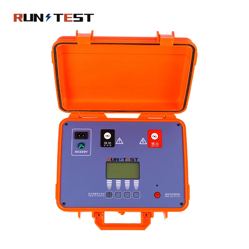
Check 4: Built for the Field: Assessing Safety, Durability, and Portability
An instrument's technical specifications are only half the story. A lightning arrester tester may have the most advanced measurement algorithms in the world, but if it cannot withstand the rigors of daily fieldwork, it is of little practical use. The environments where these tests are conducted are often harsh and unforgiving. Technicians face extreme temperatures, dust, rain, and the inherent electrical hazards of a high-voltage substation. Therefore, your fourth practical check must be a thorough assessment of the tester's physical design, focusing on its safety, durability, and portability.
Safety First, Always
Working in a live substation is an activity that demands the highest level of respect for safety. The instrument you provide to your field crews must be designed to protect them.
Electrical Isolation and Terminal Design
The current sensors (typically clamp-on CTs) and any voltage connections must be fully isolated from the main body of the instrument. This ensures that no hazardous voltages can find their way back to the operator. Examine the design of the terminals and connectors. Are they shrouded to prevent accidental contact? Are the high-voltage components, if any, clearly marked and designed to prevent user error? The Vitrek V7X series, for example, emphasizes safety features like locked HV terminals to prevent accidental exposure (Vitrek, 2025). While these are hipot testers, the design philosophy of prioritizing user safety is universal for high-voltage test equipment.
Safety Interlocks and Certifications
Many testers incorporate a wireless communication module between the main unit and the current clamps. This allows the operator to stand at a safe distance from the high-voltage equipment while the measurement is in progress, monitoring the results on a handheld display. Look for testers that are certified to relevant international safety standards, such as EN 61010. This certification is an independent verification that the product has been designed and tested to protect against electric shock and other hazards.
Durability for the Real World
The journey from the workshop to the substation and back is a tough one. The instrument will be transported in vehicles over rough roads, carried across uneven terrain, and exposed to the elements.
Ingress Protection (IP) Rating
One of the most important specifications to check is the IP rating. The IP rating is a standardized system (IEC 60529) that classifies the degree of protection provided by an enclosure against the intrusion of solid objects (like dust) and liquids (like water). The rating is given as "IP" followed by two digits.
- The first digit indicates protection against solids, from 1 (protection against objects >50mm) to 6 (completely dust-tight).
- The second digit indicates protection against liquids, from 1 (protection against dripping water) to 8 (protection against continuous immersion).
For fieldwork, you should look for a tester with a rating of at least IP54. An IP54 rating means the device is protected against dust ingress (though not fully dust-tight) and resistant to water splashes from any direction. For particularly harsh environments, such as those with frequent rain or high levels of dust like in the Middle East, a higher rating like IP65 or IP67 is highly desirable. For instance, the Power Probe VT750LCD boasts an IP65 rating, indicating it is dust-tight and can withstand water jets, making it suitable for outdoor use ().
Case Construction and Portability
Examine the physical construction of the instrument. Is it housed in a rugged, impact-resistant case? Does it have protective rubber bumpers? Some manufacturers, like voltage-tester.com, emphasize the use of durable wooden cases with foam inserts for shipping, which speaks to an understanding of the need for physical protection.
Finally, consider its size and weight. A technician may have to carry the instrument, along with other tools, a considerable distance. A compact, lightweight design will be greatly appreciated at the end of a long day. A well-designed carrying case with storage for all cables and accessories is also a sign of a thoughtfully engineered product.
| IP Rating | Solids Protection (First Digit) | Liquids Protection (Second Digit) | Field Suitability |
|---|---|---|---|
| IP54 | 5: Dust Protected (Limited ingress permitted) | 4: Splashing Water (From any direction) | Minimum for outdoor use. Suitable for mild conditions. |
| IP65 | 6: Dust Tight (No ingress of dust) | 5: Water Jets (From any direction) | Good for most field conditions, including rain and dusty sites. |
| IP67 | 6: Dust Tight (No ingress of dust) | 7: Immersion up to 1m | Excellent for harsh environments with high risk of water exposure. |
Check 5: From Data to Decisions: Analyzing Management and Connectivity
In the 21st century, the value of a test instrument is measured not only by the data it collects but also by how easily that data can be managed, analyzed, and transformed into actionable intelligence. The final practical check in your evaluation process is to scrutinize the tester's data management and connectivity features. A tester that leaves you with a notebook full of handwritten numbers is a relic of the past. A modern instrument must be a seamless part of your digital asset management ecosystem.
The goal of condition-based maintenance is to move from a reactive or time-based schedule to a proactive, predictive strategy. You want to be able to predict that an arrester is likely to fail in the next six months and replace it during a planned outage, rather than having it fail unexpectedly and cause a costly emergency. This predictive capability is built on the foundation of historical data. You need to be able to track the resistive leakage current of every arrester in your system over time.
Onboard Storage and Data Structuring
At a minimum, the tester should have sufficient internal memory to store the results of many tests. Look for an instrument that stores not just the final resistive current value but the complete test record: date, time, substation name, asset ID, all three phase readings, the measured voltage and frequency, and the ambient temperature.
A superior tester will allow you to structure this data in a logical hierarchy. You should be able to create a database of your substations and equipment directly on the instrument. When a technician goes to a site, they can simply select the specific arrester they are testing from a pre-loaded list. This eliminates typos and ensures consistent naming conventions, which is absolutely vital for the integrity of your long-term database.
Connectivity and Software
Once the data is collected, you need an efficient way to get it off the instrument and onto a central computer for analysis.
Physical and Wireless Interfaces
Look for standard connectivity options like USB or RS232 ports. A USB port allows for the quick transfer of data to a laptop or a USB flash drive. Wireless connectivity, such as Bluetooth, is a significant advantage. It allows the technician to transfer data wirelessly to a nearby laptop or tablet without fumbling with cables, further enhancing safety and efficiency. The V7X series of testers, for example, includes USB 2.0, RS232, and Digital I/O as standard interfaces, highlighting the industry's move towards comprehensive connectivity ().
Analysis and Reporting Software
The hardware is only one part of the equation; the software is equally important. The tester should come with a dedicated PC software package for data analysis and reporting. This software should allow you to:
- Import Data: Easily download test results from the instrument.
- Organize and Filter: Sort data by date, substation, voltage level, or asset ID.
- Trend Analysis: Plot the resistive leakage current of a specific arrester or a group of arresters over time. The software should make it easy to visualize trends and identify assets whose condition is deteriorating.
- Generate Reports: Create professional, standardized reports with tables and graphs at the click of a button. These reports are essential for documenting your maintenance activities, justifying budget requests for replacements, and complying with regulatory requirements.
When evaluating the software, consider its user interface. Is it intuitive and easy to navigate? Does it support the languages spoken by your technical teams? A powerful but overly complex software package may end up being underutilized. A guided tour or a trial version of the software is an excellent way to assess its suitability for your organization. By choosing a tester with a comprehensive data management solution, you are not just buying a measurement tool; you are investing in a powerful system for predictive asset management.
A Practical Guide to Field Testing Procedures
Possessing a state-of-the-art lightning arrester tester is the first step. The second, equally vital step, is knowing how to use it safely and effectively in the field. A standardized, repeatable testing procedure is the bedrock of reliable data collection. It ensures that every technician, regardless of experience level, performs the test in the same way, minimizing variables and maximizing the comparability of results over time. Let us walk through a typical field testing procedure, from initial safety checks to final data storage.
Step 1: The Pre-Test Briefing and Safety Assessment
Before any equipment is even unpacked, the work begins with a safety briefing. The entire team should review the work order, the specific arresters to be tested, and the associated electrical diagrams. A thorough risk assessment must be performed. Identify all potential hazards: the primary high voltage, adjacent energized equipment, ground potential rise, and even non-electrical hazards like weather conditions or wildlife.
Confirm that all team members have the appropriate Personal Protective Equipment (PPE), including hard hats, safety glasses, flame-retardant clothing, and properly rated high-voltage gloves if required. Ensure that the test area is clearly demarcated with safety cones or tape to keep unauthorized personnel at a safe distance. This initial phase sets the tone for a safe and professional operation.
Step 2: Instrument and Site Preparation
With the safety protocols in place, you can prepare the instrument. Power on the lightning arrester tester and perform any internal self-checks as recommended by the manufacturer. This verifies that the instrument itself is functioning correctly before you connect it to the asset.
Next, prepare the arrester. The most important connection point is the arrester's ground lead. The leakage current measurement is typically made by clamping a current transformer (CT) around this lead. It is imperative that this ground lead is clean and free of corrosion. A dirty or corroded connection can itself have a resistive component, which could be mistakenly measured as part of the arrester's leakage current. Use a wire brush to clean the connection point on the ground lead where the CT will be placed.
Crucially, ensure that the arrester's grading or corona ring is clean and properly installed. Contamination on the outside of the arrester's porcelain or polymer housing can create an alternative path for leakage current to flow along the surface. This surface leakage will be picked up by the CT along with the internal leakage current, leading to erroneously high readings. While it is not always practical to clean the entire arrester before every test, a visual inspection for heavy contamination is essential.
Step 3: Connecting the Tester
This is the most hands-on part of the process. Follow the manufacturer's instructions precisely. A typical connection for a three-phase tester using the harmonic analysis method would be as follows:
- Connect the Current Transformers (CTs): Clamp one CT around the ground lead of each of the three arresters (Phase A, B, and C). Pay close attention to the direction arrow on the CT. It must be oriented correctly with respect to the direction of current flow (from the arrester to the ground) for an accurate measurement. Connect the cables from the CTs to the corresponding input channels on the tester.
- Connect the Voltage Reference: The tester needs a voltage reference to perform harmonic compensation and phase analysis. This is often accomplished by connecting a lead from the tester's voltage input to the potential transformer (PT) or capacitive voltage transformer (CVT) secondary circuit for that bay. This provides a safe, low-voltage representation of the primary system voltage.
- Power On and Verify: Power the tester, usually from a local 110V or 220V supply in the substation control room. Once the instrument is fully booted, check the live readings. It should display plausible values for the system voltage and frequency, and an initial reading for the leakage currents. This confirms that all connections are good.
Step 4: Performing the Measurement and Storing the Data
With everything connected and verified, performing the test is often as simple as pressing a button.
- Enter Asset Information: Before starting the measurement, navigate the tester's interface to select or enter the asset information: substation, bay, and arrester ID. This links the measurement to the correct asset in your database. Input the ambient temperature and humidity, as this information is valuable for long-term analysis.
- Initiate the Test: Start the measurement sequence. The tester will acquire data for a set period, typically 30-60 seconds, to ensure a stable and averaged reading. During this time, the instrument is measuring the total leakage current and its harmonics for all three phases, as well as the system voltage and its harmonics.
- Review the Results: Once the test is complete, the tester will display the key results. The most important value is the compensated resistive leakage current (often denoted as Ir) for each phase. Good instruments will display the three phases side-by-side for easy comparison.
- Save the Record: If the results look reasonable, save the complete test record to the instrument's internal memory. Do not rely on writing it down. Saving the digital record preserves all the associated data for future analysis.
Step 5: Disconnection and Post-Test Review
After saving the data, safely disconnect all leads in the reverse order of connection. Pack the instrument and all its accessories securely in its case. Before leaving the site, it is good practice for the team to have a quick review of the results. Did any of the readings seem unusually high? Was there a significant imbalance between the phases? Making a preliminary note of any anomalies can help prioritize the detailed analysis that will happen back at the office. This structured approach ensures that every test is performed with the highest standards of safety, accuracy, and efficiency.
Interpreting the Data: A Diagnostic Primer
Collecting accurate data with a high-quality lightning arrester tester is a significant achievement, but it is only the first part of the diagnostic process. The real skill lies in interpreting that data to make informed decisions about the health of your assets. A single number in isolation is rarely enough; you must become a detective, looking at the evidence from multiple angles—comparing phases, analyzing trends over time, and considering the specific characteristics of the arrester.
The Three Pillars of Interpretation
Effective interpretation rests on three pillars: Phase Comparison, Trend Analysis, and Absolute Value Assessment.
Pillar 1: Phase Comparison (The "Snapshot" Analysis)
As discussed earlier, one of the most powerful diagnostic tools at your disposal is the simultaneous measurement of a three-phase set of arresters. This gives you an immediate, powerful "snapshot" of the situation.
- What to Look For: In a healthy and balanced system, the resistive leakage current (Ir) values for the three arresters (A, B, and C) should be very similar.
- The Red Flag: A significant difference between the phases is a major cause for concern. For example, if two phases show an Ir of 40-50 µA and the third shows 120 µA, the third arrester is highly suspect, even if 120 µA is technically below the manufacturer's absolute limit. The deviation is the key indicator.
- Possible Causes: Such an imbalance could be due to advanced aging in one unit, moisture ingress through a faulty seal on one arrester, or uneven surge history.
- Action: An arrester showing significant deviation from its peers should be flagged for further investigation and prioritized for replacement.
Pillar 2: Trend Analysis (The "Historical" Analysis)
This is the cornerstone of predictive, condition-based maintenance. By plotting the compensated resistive leakage current of an arrester over months and years, you can move from finding existing problems to predicting future ones.
- What to Look For: In a healthy arrester, the resistive leakage current should remain relatively stable over time. A slow, gradual increase is normal as the arrester ages, but this should be a very gentle slope.
- The Red Flag: A sudden "knee point" or a sharp, sustained increase in the trend line is a clear sign that the arrester's degradation is accelerating. It may be entering the early stages of thermal runaway.
- Example: An arrester might have an Ir of 60 µA for three years. In the fourth year, it jumps to 90 µA, and six months later, it is at 130 µA. This acceleration is a much more alarming sign than a steady reading of 130 µA would be on its own. It tells you that the arrester's condition is actively and rapidly worsening.
- Action: Use your analysis software to set alarm levels. An "Alert" level could be triggered by a 50% increase from the initial baseline, prompting more frequent testing. A "Critical" alarm, perhaps triggered by a 100% or 200% increase, would signal the need for immediate replacement planning. This is where a selecting a suitable arrester field tester with powerful trending software pays for itself.
Pillar 3: Absolute Value Assessment (The "Manufacturer's Guideline")
The final check is to compare the measured resistive leakage current against the absolute limits provided by the arrester's manufacturer.
- What to Look For: Manufacturers will often provide a maximum recommended resistive leakage current for a given arrester type. This value is based on their design and testing.
- The Red Flag: Any reading that exceeds the manufacturer's published limit is an immediate cause for concern.
- Important Caveat: This should be considered the last line of defense, not the first. Relying solely on absolute limits is a reactive approach. An arrester could be well on its way to failure long before it breaches the absolute maximum. For example, if the limit is 500 µA, an arrester that has jumped from 50 µA to 250 µA is far more worrying than one that has been stable at 300 µA for five years.
- Action: An arrester exceeding its absolute limit should be scheduled for replacement as soon as possible.
By combining these three pillars, you can build a comprehensive and nuanced picture of your arrester population's health. You can move beyond simple pass/fail testing and implement a truly intelligent asset management strategy, ensuring the continued safety and reliability of your power system.
Frequently Asked Questions (FAQ)
What is the difference between total leakage current and resistive leakage current?
Total leakage current is the overall current that flows through a lightning arrester under normal operating voltage. It is composed of two parts: a large capacitive component, which is due to the physical construction of the arrester, and a very small resistive component. The resistive leakage current is the part that flows through the metal-oxide (MOV) blocks and is the key indicator of degradation. An increase in the resistive component signals that the arrester is aging and at a higher risk of failure.
Why is it necessary to test lightning arresters?
Lightning arresters degrade over time due to exposure to voltage stress, temperature, moisture, and the surges they divert. This degradation is invisible from the outside but leads to an increase in resistive leakage current, which can cause the arrester to overheat and fail catastrophically in a process called thermal runaway. Regular testing with specialized lightning arrester testers is the only way to detect this degradation early and replace the arrester before it fails, preventing damage to expensive equipment and avoiding power outages.
How often should I test my lightning arresters?
The optimal testing frequency depends on several factors, including the age of the arrester, the criticality of the equipment it protects, and the environmental conditions. A common starting point is every 2 to 5 years. However, for older arresters, those in areas with high lightning activity (like parts of South America or South Africa), or those protecting critical transformers, an annual test is often recommended. The results of trend analysis should also guide your frequency; if an arrester shows a trend of increasing resistive current, the testing interval for that unit should be shortened.
Can I use a standard insulation resistance tester to check a lightning arrester?
No, a standard insulation resistance tester (like those found at ) is not suitable for diagnosing the condition of modern MOV-type lightning arresters. An insulation resistance test applies a DC voltage and measures resistance, which will not provide the crucial resistive leakage current value under AC operating conditions. It may be used to check for severe damage or short circuits, but it cannot perform the nuanced health assessment needed for predictive maintenance. You need a dedicated lightning arrester tester that can operate on an energized arrester and separate the resistive and capacitive current components.
What does the third harmonic measurement tell me about the arrester?
The metal-oxide blocks in an arrester have a non-linear voltage-current characteristic. When the sinusoidal AC system voltage is applied, the resistive component of the leakage current becomes distorted and contains odd harmonics, with the third harmonic being the most significant. The capacitive current remains a pure sine wave. Therefore, by measuring the magnitude of the third harmonic in the total leakage current (and compensating for any harmonics in the voltage), a tester can accurately calculate the resistive leakage current, which is the primary indicator of the arrester's health.
Is it better to test an arrester online (energized) or offline (de-energized)?
Modern lightning arrester testing is almost exclusively performed online. Online testing offers several advantages: it is faster, does not require a system outage, and it measures the arrester's performance under its actual operating conditions, providing the most realistic data. Offline tests, which may involve applying a variable AC or DC voltage, are generally reserved for laboratory analysis or special investigations and are not practical for routine field maintenance.
What is the importance of a tester's IP rating?
The Ingress Protection (IP) rating indicates how well the instrument is sealed against dust and water. For fieldwork in regions like the Middle East (dust) or Southeast Asia (rain), a high IP rating (e.g., IP65) is vital. It ensures the tester's internal electronics are protected from the elements, guaranteeing long-term reliability and preventing premature failure of the testing equipment itself.
Conclusion
The selection of a lightning arrester tester is a decision that resonates through the core of a power system's reliability strategy. It is an investment not merely in a piece of hardware, but in the capacity for foresight—the ability to identify and mitigate a failure before it occurs. As we have explored, a truly effective instrument is defined by its nuanced understanding of arrester physics. It must possess the acuity to isolate the subtle signature of degradation—the resistive leakage current—from the overwhelming noise of the capacitive current. It must have the intelligence to compensate for the real-world fluctuations of voltage and frequency, ensuring that the data collected today is directly comparable to the data collected years from now.
For the engineers and technicians working in the diverse and demanding environments of South America, Russia, Southeast Asia, the Middle East, and South Africa, the choice is even more significant. The instrument must be more than just accurate; it must be a reliable partner in the field. Its design must prioritize the safety of the operator above all else. Its construction must be robust enough to endure the dust of the desert and the humidity of the tropics. Its software must transform raw data into clear, actionable intelligence, enabling the shift from reactive repairs to a proactive, predictive maintenance culture. By systematically applying the practical checks outlined—evaluating measurement capability, compensation features, three-phase functionality, physical durability, and data management—you can confidently select an instrument that will empower you to protect your critical assets, enhance grid stability, and ensure the uninterrupted flow of power to the communities you serve.
References
RUN-TEST Electric. (2025). China transformer test and resistance tester manufacturer. Voltage-tester.com. Retrieved from
RUN-TEST Electric. (2025). Why choose us. Voltage-tester.com. Retrieved from https://www.voltage-tester.com/why-choose-us/