
เครื่องกำเนิดกระแสหลัก
เครื่องกำเนิดกระแสไฟฟ้าหลัก (ซึ่งอยู่ใน ชุดทดสอบการฉีดกระแสหลัก) เป็นอุปกรณ์ที่ใช้สร้างกระแสไฟฟ้าที่มีค่าคงที่และทราบแน่ชัด เพื่อใช้ในการทดสอบและปรับเทียบในระบบไฟฟ้า อุปกรณ์นี้มักถูกใช้ในแอปพลิเคชันต่าง ๆ เช่น การทดสอบการทำงานของรีเลย์ป้องกัน, ตัวแปลงกระแส (CTs) และอุปกรณ์วัดอื่น ๆ เพื่อรับรองว่าอุปกรณ์เหล่านั้นทำงานได้อย่างแม่นยำภายใต้เงื่อนไขที่กำหนด
-
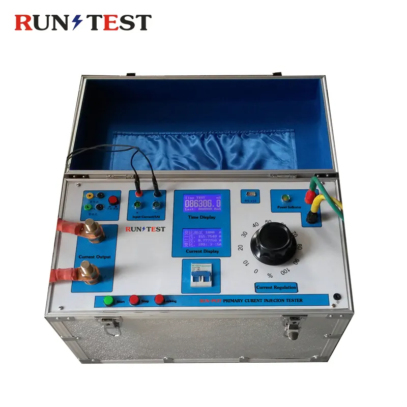
เครื่องกำเนิดกระแสไฟฟ้าขนาดใหญ่ 1000A เครื่องทดสอบการฉีดกระแสไฟฟ้าหลัก
-
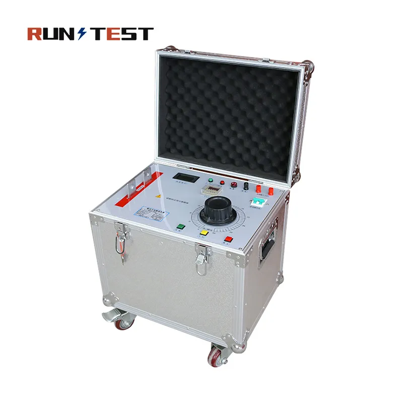
เครื่องฉีดกระแสหลักขนาดใหญ่/เครื่องกำเนิดกระแสสูงแบบบูรณาการหลัก
เครื่องกำเนิดกระแสหลักเป็นอุปกรณ์ที่จำเป็นสำหรับการทดสอบและตรวจสอบระบบไฟฟ้า ไม่ว่าจะเป็นรีเลย์ป้องกัน, หม้อแปลงกระแส, สวิตช์ตัดวงจร หรืออุปกรณ์อื่นใดก็ตาม อุปกรณ์เหล่านี้คือสิ่งที่ช่วยให้เราสามารถจำลองกระแสผิดปกติได้อย่างแม่นยำ ความสามารถที่ยอดเยี่ยมและการควบคุมกระแสอย่างเต็มที่ของอุปกรณ์เหล่านี้สามารถช่วยเราได้อย่างมากในการมั่นใจว่าระบบป้องกันและระบบวัดค่าทางไฟฟ้าทำงานได้อย่างถูกต้อง และไม่ก่อให้เกิดความเสียหายต่ออุปกรณ์
วัตถุประสงค์ของเครื่องกำเนิดกระแสหลัก
- การทดสอบรีเลย์ป้องกัน: เราใช้กระแสไฟฟ้าที่คาดการณ์ไว้เพื่อตรวจสอบว่ารีเลย์ป้องกันทำงานอย่างถูกต้องหรือไม่ ซึ่งช่วยรับประกันว่ารีเลย์เหล่านี้จะตอบสนองอย่างถูกต้องเมื่อเกิดปัญหาทางไฟฟ้าจริง
- การทดสอบเครื่องแปลงกระแส (CT): CT สามารถสร้างวงจรด้วยระดับกระแสไฟฟ้าต่ำเพื่อวัดระบบป้องกันหรือระบบผลิตไฟฟ้าได้ เราสามารถทดสอบ CT เพื่อตรวจสอบว่าทำงานได้อย่างมีประสิทธิภาพและสามารถปฏิบัติหน้าที่ได้
- การสอบเทียบเครื่องมือวัด: เราสามารถใช้เครื่องกำเนิดกระแสหลักเพื่อตรวจสอบมิเตอร์วัดกระแส มิเตอร์วัดกำลัง และเครื่องมือวัดค่าไฟฟ้าอื่น ๆ ได้ ด้วยวิธีนี้ เราจึงสามารถตรวจสอบให้แน่ใจว่าเครื่องมือเหล่านี้แสดงค่าได้อย่างถูกต้อง
- การทดสอบเบรกเกอร์วงจร: เราตรวจสอบว่าเบรกเกอร์สามารถรับมือกับกระแสผิดปกติที่อาจเกิดขึ้นได้หรือไม่ และทำงานภายในระยะเวลาที่กำหนด ด้วยวิธีนี้ เราจึงมั่นใจได้ว่าเบรกเกอร์จะปกป้องระบบได้เมื่อเกิดความผิดปกติทางไฟฟ้า
ข้อดีของเครื่องกำเนิดไฟฟ้ากระแสหลัก
- การทดสอบที่แม่นยำ: เครื่องกำเนิดไฟฟ้าเหล่านี้ช่วยให้เราสามารถทดสอบอุปกรณ์ป้องกันได้อย่างน่าเชื่อถือ เราจึงมั่นใจได้ว่าอุปกรณ์เหล่านี้จะทำงานได้อย่างถูกต้องเมื่อเกิดข้อผิดพลาดจริง
- ความหลากหลาย: อุปกรณ์เหล่านี้สามารถผลิตทั้งกระแสไฟฟ้าสลับ (AC) และกระแสไฟฟ้าตรง (DC) ได้ ความยืดหยุ่นนี้ทำให้อุปกรณ์เหล่านี้มีประโยชน์ในการใช้งานที่หลากหลาย ตั้งแต่การทดสอบแบบง่ายๆ ไปจนถึงโครงการไฟฟ้าที่ซับซ้อน
- ประสิทธิภาพ: เครื่องกำเนิดกระแสหลักช่วยให้เราทดสอบและปรับเทียบระบบไฟฟ้าได้อย่างรวดเร็ว เราสามารถเสร็จสิ้นงานได้อย่างรวดเร็ว ซึ่งช่วยลดเวลาหยุดทำงานและทำให้ระบบมีความน่าเชื่อถือมากขึ้น
- ความทนทาน: เครื่องกำเนิดไฟฟ้าเหล่านี้ได้รับการออกแบบให้ทนทาน สามารถรับมือกับสภาพการใช้งานที่หนักหน่วงในการทดสอบภาคสนามได้ ผลิตมาเพื่อใช้งานได้ยาวนาน ทำให้เราสามารถใช้งานได้นานโดยไม่ต้องกังวล
ตารางคุณสมบัติทางเทคนิค
| คุณสมบัติหลักของซีรีส์ Core | ข้อมูลทางเทคนิคและช่วงการใช้งาน | ประโยชน์สำหรับลูกค้า |
| ช่วงค่าออกปัจจุบัน | 200A, 500A, 1000A, 2000A, 5000A จนถึง 10000A AC/DC | ตอบสนองความต้องการที่หลากหลาย ตั้งแต่สวิตช์ตัดวงจรแรงดันต่ำขนาดเล็ก ไปจนถึงสถานีไฟฟ้าย่อยแรงดันสูงขนาดใหญ่ |
| ระดับความแม่นยำของผลลัพธ์ | ±0.5% หรือ ±1.0% (หน้าจอแสดงผลดิจิทัล True RMS) | ให้ความแม่นยำสูงในการตั้งค่าการป้องกันและการปรับเทียบ |
| การตั้งค่าวงจรการทำงาน | ระยะเวลาสั้น (5 นาที) / แบบเป็นช่วง / แบบต่อเนื่อง (24 ชั่วโมง) | ช่วยสร้างสมดุลระหว่างการตรวจสอบแบบรวดเร็วแบบพกพาและการทดสอบความร้อนของบัสบาร์ในระยะเวลานาน |
| สถาปัตยกรรมการควบคุม | ระบบควบคุม Variac แบบมือ / หน้าจอสัมผัสไมโครคอมพิวเตอร์อัจฉริยะ | เหมาะสำหรับหลายสถานการณ์: การตรวจสอบอย่างรวดเร็วในสนาม หรือสคริปต์ห้องปฏิบัติการแบบอัตโนมัติ |
| ระบบติดตามด้วยมิเตอร์คู่ | หน้าจอแสดงกระแสไฟฟ้าแบบบูรณาการสำหรับระดับปฐมศึกษาและมัธยมศึกษา พร้อมด้วยระบบตรรกะขั้ว | ช่วยลดความจำเป็นในการใช้เครื่องวัดภายนอก โดยแสดงอัตราส่วนการหมุนและมุมเฟสโดยอัตโนมัติ |
| การป้องกันระดับสูง | ระบบล็อกกันทางอิเล็กทรอนิกส์สำหรับกระแสเกิน แรงดันเกิน และการเริ่มต้นจากศูนย์ | ช่วยป้องกันผู้ปฏิบัติงานในสถานที่และวัตถุทดสอบที่มีมูลค่าสูงจากความเสียหายได้อย่างเต็มที่ |
วิธีเลือกเครื่องกำเนิดกระแสหลัก
การเลือกเครื่องกำเนิดกระแสหลักที่เหมาะสมจำเป็นต้องพิจารณาให้สมดุลระหว่างข้อมูลทางเทคนิคกับข้อจำกัดในสถานที่จริง เพื่อเพิ่มประสิทธิภาพผลตอบแทนจากการลงทุน (ROI) ในการจัดซื้อ ให้ประเมินปัจจัยหลัก 5 ประการต่อไปนี้:
1. กระแสไฟฟ้าออกสูงสุด
กำหนดกระแสผิดปกติสูงสุดที่คุณต้องการจำลอง สำหรับการทดสอบเบรกเกอร์แบบตัวเรือนหล่อแรงดันต่ำ (LV) ระบบที่มีกระแส 500A ถึง 1000A จะทำงานได้ดี อย่างไรก็ตาม การทดสอบระบบสถานีไฟฟ้าระดับแรงดันสูง (HV) จำเป็นต้องใช้กระแส 2000A ถึง 5000A เพื่อให้ถึงค่าเกณฑ์การตัดวงจรของเส้นโค้งเวลา-กระแสแบบผกผัน
2. รอบการทำงานต่อเนื่องและเวลาทำงาน
พิจารณาว่าการทดสอบของคุณต้องการการดำเนินการอย่างรวดเร็วหรือการรักษาอุณหภูมิเป็นเวลานาน การทดสอบเวลาตัดวงจรมาตรฐานใช้เวลาเพียงไม่กี่วินาที สำหรับการทดสอบประเภทนี้ การใช้รอบการทำงานระยะสั้นจะช่วยลดค่าใช้จ่ายได้ ส่วนการทดสอบการเพิ่มขึ้นของอุณหภูมิบนบัสบาร์ (Busbar Temperature Rise Test) กลับต้องการกระแสไฟฟ้าที่คงที่และไม่ถูกขัดจังหวะเป็นเวลาหลายชั่วโมง โดยไม่ทำให้อุปกรณ์ร้อนเกิน
3. ลักษณะของวัตถุทดสอบ
ค่าอิมพีแดนซ์ของโหลดจะส่งผลต่อกำลังออกที่ต้องการของเครื่องกำเนิดไฟฟ้า (kVA) วัตถุทดสอบที่มีน้ำหนักมาก เช่น สายเคเบิลที่ยาว จำเป็นต้องใช้แรงดันออกในสภาพวงจรเปิดที่สูงขึ้น ให้ตรวจสอบกำลัง VA ของเครื่องฉีดน้ำมันเสมอ พร้อมกับค่ากระแสไฟฟ้าสูงสุดที่กำหนดไว้
4. ความสะดวกในการพกพาและความคล่องตัว
การทดสอบภาคสนามในสถานีไฟฟ้าย่อยที่ห่างไกลต้องการความคล่องตัว สำหรับสภาพแวดล้อมเหล่านี้ ควรเลือกระบบแบบกระเป๋าเดินทางที่รวมเป็นหนึ่งและพกพาได้ ซึ่งช่างเทคนิคสองคนสามารถยกขึ้นได้อย่างง่ายดาย ส่วนสำหรับห้องปฏิบัติการอุตสาหกรรมแบบถาวรหรือโรงงานผลิตอุปกรณ์สวิตช์เกียร์ หน่วยที่ติดตั้งบนรถเข็นแบบทนทานพร้อมล้อเลื่อนที่แข็งแรงจะให้ความสะดวกในการใช้งานที่ดีกว่า
5. โหมดการควบคุมและระบบอัตโนมัติ
การควบคุมด้วยมือผ่านปุ่มหมุน Variac ที่ออกแบบตามหลักการยศาสตร์ ให้ความน่าเชื่อถือสูงและคุ้มค่าด้านต้นทุน ทีมงานบำรุงรักษาแบบดั้งเดิมมักนิยมใช้ระบบนี้สำหรับการตรวจสอบอย่างรวดเร็ว อย่างไรก็ตาม ห้องปฏิบัติการไฟฟ้าสมัยใหม่ได้รับประโยชน์จากอินเทอร์เฟซหน้าจอสัมผัส PLC อัจฉริยะ ระบบอัตโนมัติรองรับโปรไฟล์การทดสอบที่ตั้งโปรแกรมไว้ล่วงหน้า การบันทึกข้อมูล และการสร้างรายงานดิจิทัลทันที
การใช้งานในอุตสาหกรรม
บริษัทไฟฟ้า
บริษัทไฟฟ้าพึ่งพาชุดทดสอบการฉีดกระแสหลักอย่างมากเพื่อรักษาความทนทานของระบบไฟฟ้า ในช่วงที่หยุดการดำเนินงานเพื่อบำรุงรักษา ช่างเทคนิคจะใช้เครื่องกำเนิดไฟฟ้าเหล่านี้เพื่อตรวจสอบว่าสถานีย่อยแรงสูงสามารถตัดกระแสเกินได้อย่างแม่นยำ ซึ่งช่วยยืนยันว่าวงจรทำงานอย่างสมบูรณ์และปกป้องโครงสร้างพื้นฐานจากปัญหาการลัดวงจร
ผู้ผลิตเครื่องแปลงแรงดัน
สำหรับผู้ผลิตหม้อแปลง การควบคุมคุณภาพจำเป็นต้องมีการทดสอบอย่างเข้มงวดก่อนการรับมอบจากโรงงาน ผู้เทคนิคใช้เครื่องกำเนิดกระแสหลักเพื่อตรวจสอบอัตราส่วนรอบขดลวด การยืนยันขั้ว และการตรวจสอบการอิ่มตัวทางแม่เหล็ก ซึ่งช่วยรับประกันว่าผลิตภัณฑ์เป็นไปตามมาตรฐานการวัดและการป้องกันระดับสากลก่อนการจัดส่ง
สถานีไฟฟ้าย่อย
วิศวกรภาคสนามใช้เครื่องกำเนิดกระแสสูงของเราในช่วงขั้นตอนการทดสอบและรับมอบสถานีไฟฟ้าย่อยที่สำคัญ โดยส่งกระแสไฟฟ้าเข้าไปโดยตรงในระบบบัสบาร์หลัก เพื่อพิสูจน์ว่าเครือข่ายระบบป้องกันทั้งหมดทำงานได้อย่างสมบูรณ์ ซึ่งการตรวจสอบนี้ครอบคลุมระบบบัสบาร์หลัก ตัวแปลงกระแส (CT) และระบบสายไฟรอง
ห้องปฏิบัติการไฟฟ้า
ห้องปฏิบัติการสอบเทียบและทดสอบที่ได้รับการรับรองต้องการความแม่นยำในการวัดในระดับสูงสุด เครื่องกำเนิดกระแสหลักของเราให้แหล่งกระแสที่มีความเสถียรสูงและมีความเพี้ยนต่ำเป็นพิเศษ ซึ่งช่วยให้ผู้เชี่ยวชาญด้านมาตรวิทยาสามารถสอบเทียบมิเตอร์วัดกระแสไฟฟ้าอุตสาหกรรม รีเลย์เทอร์โมแมกเนติก และเครื่องวิเคราะห์กำลังไฟฟ้าแบบดิจิทัล ภายใต้การควบคุมสภาพแวดล้อมที่เข้มงวด
โรงงานผลิตอุปกรณ์สวิตช์เกียร์
ในโรงงานผลิตอุปกรณ์สวิตช์เกียร์ที่มีกำลังการผลิตสูง ความประสิทธิภาพและการอัตโนมัติเป็นปัจจัยสำคัญ ผู้ผลิตได้นำระบบฉีดกระแสไฟฟ้าแบบหน้าจอสัมผัสอัจฉริยะของเราไปบูรณาการเข้ากับสายการผลิต ซึ่งช่วยให้ทีมควบคุมคุณภาพสามารถดำเนินการทดสอบตามขั้นตอนประจำได้อย่างรวดเร็วและเป็นไปตามมาตรฐาน สำหรับตู้สวิตช์เกียร์ เพื่อรับประกันว่าทุกหน่วยจะทำงานตัดวงจรได้อย่างถูกต้อง
พลังงานหมุนเวียน
โรงไฟฟ้าลมและระบบผลิตไฟฟ้าจากพลังงานแสงอาทิตย์ทำงานในสภาพแวดล้อมที่รุนแรง พร้อมด้วยรูปแบบการผลิตไฟฟ้าที่ผันผวน เครื่องกำเนิดกระแสหลักมีบทบาทสำคัญในการตรวจสอบแผงป้องกันพิเศษภายในสถานีย่อยเพิ่มแรงดัน ซึ่งช่วยรับประกันการทำงานที่เสถียรแม้เกิดการผันผวนของระบบไฟฟ้า และปกป้องเครื่องกำเนิดไฟฟ้าของกังหันลม
รถไฟ
ระบบรถไฟฟ้าใต้ดินและเครือข่ายรถไฟความเร็วสูงต้องพึ่งพาระบบพลังงานลากจูงแบบหนัก เครื่องฉีดกระแสไฟฟ้ากระแสสูงเฉพาะทางของเราสามารถจำลองกระแสไฟฟ้าเริ่มต้นที่รุนแรงและโหลดสูงของหัวรถจักรไฟฟ้าได้ เครื่องนี้ใช้ทดสอบเบรกเกอร์วงจรรางรถไฟและรีเลย์ป้องกันความเร็วสูง เพื่อป้องกันการดับไฟ
การบำรุงรักษาอุตสาหกรรม
โรงงานอุตสาหกรรมขนาดใหญ่ — เช่น โรงกลั่นเคมีและศูนย์ข้อมูลขนาดใหญ่ — ไม่สามารถรับมือกับการหยุดจ่ายไฟฟ้าแบบไม่คาดคิดได้ ทีมบำรุงรักษาโรงงานจึงใช้ชุดอุปกรณ์ฉีดหลักแบบพกพาในช่วงที่ปิดระบบตามกำหนดการ เพื่อตรวจสอบรีเลย์ความร้อนและเบรกเกอร์อากาศที่เริ่มเก่า เพื่อรับประกันว่ากระบวนการทำงานจะไม่ถูกขัดจังหวะ
การทดสอบแอปพลิเคชัน
-
การทดสอบเครื่องแปลงกระแส: ส่งกระแสไฟฟ้าสูงเข้าไปโดยตรงในขดลวดหลัก เพื่อประเมินอัตราส่วนรอบของ CT ความผิดพลาดของมุมเฟส และขั้วแม่เหล็ก
-
การทดสอบเบรกเกอร์วงจร: วัดเวลาการหน่วงการตัดวงจรอย่างแม่นยำของเบรกเกอร์วงจรอากาศ (ACB) และเบรกเกอร์วงจรแบบตัวเรือนหล่อ (MCCB) ภายใต้โหลดความร้อน
-
การทดสอบระบบป้องกันรีเลย์: ให้การจำลองข้อผิดพลาดหลักที่สมจริง เพื่อตรวจสอบว่ารีเลย์กระแสเกินได้รับสัญญาณที่ถูกต้องและทำงานตามลำดับการตัดวงจร
-
การทดสอบการเพิ่มขึ้นของอุณหภูมิบนบัสบาร์: ให้กระแสไฟฟ้าต่อเนื่องที่เสถียรและทนทานเป็นเวลานานหลายชั่วโมง เพื่อสังเกตการขยายตัวทางความร้อนของบัสบาร์ทองแดง
-
การทดสอบการฉีดขั้นต้น: ดำเนินการตรวจสอบอย่างละเอียดครบถ้วนของเส้นทางป้องกันทั้งหมด โดยแทนที่การคำนวณทางทฤษฎีด้วยการตรวจสอบกระแสไฟฟ้าจริง
-
การทดสอบระบบป้องกัน: ยืนยันว่าไม่มีความผิดพลาดในการเดินสายหรือขั้วไฟฟ้ากลับด้านเหลืออยู่หลังการติดตั้ง ซึ่งช่วยป้องกันจุดบอดในการป้องกันที่อาจก่อให้เกิดอันตรายระหว่างการส่งมอบ
ขั้นตอนการทดสอบ
-
ขั้นตอนที่ 1: เชื่อมต่ออุปกรณ์
โปรดตรวจสอบให้แน่ใจว่าได้ตัดการเชื่อมต่อแหล่งจ่ายไฟหลักก่อนที่จะทำการเชื่อมต่อใดๆ ให้ต่อสายออกที่มีกำลังสูงและทนกระแสสูงเข้ากับขั้วหลักของวัตถุที่ทดสอบอย่างแน่นหนา การเชื่อมต่อที่แน่นหนาจะช่วยลดความต้านทานการสัมผัสและป้องกันการร้อนเกินในจุดเฉพาะ
-
ขั้นตอนที่ 2: ตรวจสอบการต่อดิน
ต่อขั้วต่อสายดินแบบทองแดงที่ออกแบบมาโดยเฉพาะบนเครื่องวัดให้แน่นกับระบบสายดินของสถานที่ การต่อสายดินอย่างถูกต้องจะสร้างเส้นทางสำคัญสำหรับการปล่อยประจุไฟฟ้าสถิตที่ลอยตัว ขั้นตอนนี้รับประกันความปลอดภัยอย่างสมบูรณ์สำหรับเจ้าหน้าที่ที่ดำเนินการทดสอบ
-
ขั้นตอนที่ 3: ตั้งค่ากระแสไฟฟ้าขาออก
เปิดเครื่องควบคุมหลัก ใช้ทั้งปุ่มปรับวาริแอคแบบมือหรือหน้าจอสัมผัสดิจิทัลเพื่อตั้งค่ากระแสไฟฟ้าเป้าหมาย ในขั้นตอนนี้ ให้ตั้งเวลาสูงสุดที่อนุญาตหรือเส้นโค้งตัดวงจรมาตรฐาน
-
ขั้นตอนที่ 4: ส่งกระแสไฟฟ้า
ตรวจสอบว่าระบบตรงตามเกณฑ์ความปลอดภัย เช่น การตรวจสอบระบบล็อคกันเริ่มต้นที่ศูนย์ จากนั้น กดปุ่มเริ่มต้น ระบบจะเพิ่มกระแสไฟฟ้าสูงตามเป้าหมายเข้าสู่ลูปหลักอย่างราบรื่น และเริ่มทำงานของตัวจับเวลาภายใน
-
ขั้นตอนที่ 5: บันทึกผล
ติดตามค่า RMS ที่แท้จริงบนหน้าจอดิจิทัลอย่างใกล้ชิดขณะที่กระแสไฟฟ้าไหล เมื่อเบรกเกอร์ตัดการทำงาน ระบบจะหยุดทำงานทันทีและบันทึกข้อมูลสำคัญ ซึ่งรวมถึงระดับกระแสไฟฟ้าที่ป้อนเข้าอย่างแม่นยำ เวลาตัดการทำงานรวม และข้อมูลป้อนกลับจากระบบทุติยภูมิ
-
ขั้นตอนที่ 6: สร้างรายงาน
ปิดช่องสัญญาณออกปัจจุบันอย่างปลอดภัย ใช้พอร์ต USB ที่ติดตั้งมาพร้อมเครื่องหรือซอฟต์แวร์บนคอมพิวเตอร์เพื่อส่งออกบันทึกผลการทดสอบที่บันทึกไว้ ซอฟต์แวร์ระบบจะรวบรวมข้อมูลเหล่านี้เป็นรายงานการตรวจสอบแบบ PDF ที่มืออาชีพ เพื่อส่งให้ลูกค้าของคุณ
มาตรฐานอุตสาหกรรมและการปฏิบัติตามข้อกำหนด
แบบแปลนทางวิศวกรรมและหลักการผลิตของเราเป็นไปตามมาตรฐานสากลที่เข้มงวด เราออกแบบ ผลิต และปรับเทียบเครื่องกำเนิดกระแสหลักของเราตามกรอบการปฏิบัติตามมาตรฐานที่เคร่งครัดดังต่อไปนี้:
-
IEC 60044: รับประกันว่าโปรไฟล์การฉีดกระแสสูงและช่องวัดจะสอดคล้องกับพารามิเตอร์มาตรฐานสำหรับการทดสอบเครื่องแปลงสัญญาณ
-
IEC 61850: เครื่องกำเนิดไฟฟ้าซีรีส์อัจฉริยะของเรามีคุณสมบัติการบูรณาการระบบการสื่อสารแบบเลือกใช้ เพื่อทดสอบสถานีไฟฟ้าย่อยอัจฉริยะและระบบป้องกันอุปกรณ์อิเล็กทรอนิกส์อัจฉริยะ (IED) ได้อย่างราบรื่น
-
IEC 60255: รับประกันว่าการวัดความแม่นยำและเวลาตอบสนองต่อขั้นตอนของระบบของเราสามารถตรวจสอบรีเลย์วัดและอุปกรณ์ป้องกันได้อย่างแม่นยำ
-
มาตรฐาน IEEE: ปรับระบบของเราให้สอดคล้องกับมาตรฐานวิศวกรรมของอเมริกาเหนือ (เช่น ซีรีส์ IEEE C37) สำหรับการทดสอบเบรกเกอร์วงจรไฟฟ้า
-
ISO 9001: ทุกขั้นตอนของการผลิต ตั้งแต่การจัดหาชิ้นส่วนไปจนถึงการประกอบทางกล ล้วนปฏิบัติตามขั้นตอนของระบบการจัดการคุณภาพอย่างเคร่งครัด เพื่อรับประกันความสม่ำเสมอ
-
การปฏิบัติตามมาตรฐาน CE: สอดคล้องกับข้อกำหนดของคำสั่งเกี่ยวกับแรงดันต่ำ (LVD) และข้อกำหนดเกี่ยวกับความเข้ากันได้ทางแม่เหล็กไฟฟ้า (EMC) ของยุโรปอย่างครบถ้วน ซึ่งช่วยรับประกันความปลอดภัยและลดการรบกวนความถี่วิทยุให้น้อยที่สุด
การรับประกันคุณภาพ
คุณภาพคือเส้นชีวิตของบริษัทเรา เราใช้ขั้นตอนการตรวจสอบที่ครอบคลุมและไม่มีข้อผิดพลาดกับเครื่องกำเนิดกระแสหลักทุกเครื่องก่อนส่งสินค้า:
-
การตรวจสอบสินค้าเข้า: เราดำเนินการตรวจสอบวัตถุดิบอย่างเคร่งครัด แกนเหล็กซิลิคอน ขดลวดทองแดง และไมโครชิปดิจิทัล ต้องผ่านการทดสอบความทนทานอย่างเข้มงวดก่อนที่จะส่งไปยังขั้นตอนการประกอบ
-
ขั้นตอนการประกอบ: ช่างไฟฟ้าอุตสาหกรรมที่ได้รับการฝึกอบรมอย่างมืออาชีพจะประกอบตัวเครื่องโดยใช้เทคนิคการสร้างโครงเพื่อลดการสั่นสะเทือน ซึ่งช่วยให้เครื่องแปลงไฟฟ้าภายในที่มีน้ำหนักมากสามารถทนต่อการขนส่งที่สมบุกสมบันได้
-
ขั้นตอนการปรับเทียบ: ช่างเทคนิคจะปรับเทียบตัวแปลงกระแสและเซ็นเซอร์ทุกชิ้นที่ติดตั้งภายในเครื่องวัด โดยใช้มาตรฐานอ้างอิงที่มีความแม่นยำสูง ซึ่งสามารถตรวจสอบย้อนกลับได้ถึงสถาบันมาตรวิทยาแห่งชาติ
-
การทดสอบความทนทาน: เครื่องกำเนิดไฟฟ้าที่ผลิตเสร็จแล้วจะถูกนำเข้าสู่ห้องทดสอบโหลดเฉพาะทางของเรา เพื่อทำงานที่กระแสไฟฟ้าออกสูงสุดตามค่ากำหนด ซึ่งการทดสอบนี้ช่วยประเมินความเสถียรทางความร้อน และรับประกันว่าส่วนประกอบระบบระบายความร้อนทำงานได้อย่างสมบูรณ์
-
การทดสอบความแม่นยำของผลลัพธ์: เราใช้ออสซิลโลสโคปแบบเก็บข้อมูลดิจิทัลและเครื่องวิเคราะห์กำลังไฟฟ้าเพื่อตรวจสอบรูปคลื่นของกระแสไฟฟ้าขาออก ซึ่งช่วยยืนยันว่าอุปกรณ์ดังกล่าวตรงกับระดับความแม่นยำที่กำหนด
-
การตรวจสอบครั้งสุดท้าย: การตรวจสอบครั้งสุดท้ายจะตรวจสอบระบบล็อคความปลอดภัยทั้งหมด ปุ่มหยุดฉุกเฉิน และความต้านทานฉนวน เมื่อเสร็จสิ้นแล้ว เราจะออกหมายเลขติดตามเฉพาะและใบรับรองการทดสอบจากโรงงาน
คำถามที่พบบ่อย
คำถามที่ 1: เครื่องกำเนิดกระแสหลักคืออะไร?
A: เครื่องกำเนิดกระแสหลักเป็นอุปกรณ์ทดสอบเฉพาะทางที่มีความจุสูงและแรงดันต่ำ ซึ่งสามารถส่งกระแสไฟฟ้าสูงเข้าไปโดยตรงในเส้นทางหลักของระบบไฟฟ้าได้อย่างปลอดภัย เพื่อประเมินประสิทธิภาพของระบบป้องกัน
คำถามที่ 2: การทดสอบการฉีดหลักคืออะไร?
A: การทดสอบการฉีดกระแสหลักเป็นวิธีการตรวจสอบความถูกต้องทางไฟฟ้าแบบครบวงจร โดยฉีดกระแสไฟฟ้าสูงเข้าสู่ด้านหลักของอุปกรณ์ เพื่อทดสอบระบบป้องกันทั้งหมด รวมถึงเซ็นเซอร์ สายไฟ และรีเลย์
คำถามที่ 3: ความแตกต่างระหว่างการทดสอบการฉีดขั้นต้นและการทดสอบการฉีดขั้นทุติยภูมิคืออะไร?
A: การฉีดสัญญาณหลักจะส่งกระแสไฟฟ้าสูงระดับเต็มไปยังวงจรหลัก เพื่อทดสอบวงจรทั้งหมดภายใต้สภาวะความเครียด ส่วนการฉีดสัญญาณรองจะข้ามเซ็นเซอร์หลักไป และส่งสัญญาณระดับต่ำไปยังรีเลย์โดยตรง
คำถามที่ 4: ฉันต้องการกระแสไฟฟ้าเท่าใดสำหรับแอปพลิเคชันของฉัน?
A: สิ่งนี้ขึ้นอยู่กับข้อกำหนดของวัตถุทดสอบของคุณ สำหรับ MCCB แรงดันต่ำแบบมาตรฐาน รุ่นที่มีกระแส 500A–1000A ก็เพียงพอแล้ว ส่วนสำหรับเบรกเกอร์แรงดันสูง ให้เลือกอุปกรณ์ที่มีกระแส 2000A ถึง 5000A หรือสูงกว่า
คำถามที่ 5: สามารถปรับกระแสไฟฟ้าขาออกให้เหมาะสมกับความต้องการเฉพาะของโรงงานเราได้หรือไม่?
A: ใช่ครับ เรามีบริการ OEM และบริการปรับแต่งตามความต้องการอย่างครบถ้วน เราสามารถปรับแต่งค่ากระแสไฟฟ้าสูงสุด การจัดรูปแบบหลายเฟส รูปแบบตัวเครื่องพิเศษ ความยาวสายตามความต้องการ หรือซอฟต์แวร์ควบคุมอัตโนมัติได้
คำถามที่ 6: การส่งออกกระแสสูงอย่างต่อเนื่องสามารถทำงานได้นานเท่าใด?
A: ขึ้นอยู่กับรูปแบบการตั้งค่าของเครื่อง รุ่นมาตรฐานมีรอบการทำงานระยะสั้นที่ได้รับการปรับให้เหมาะสมสำหรับการตรวจสอบอย่างรวดเร็ว ส่วนสำหรับการทดสอบความร้อนแบบเฉพาะทาง เราได้ออกแบบรุ่นที่ทำงานต่อเนื่องโดยเฉพาะ เพื่อให้สามารถทำงานได้โดยไม่หยุดชะงัก
คำถามที่ 7: การซื้อสินค้านี้มาพร้อมกับใบรับรองการสอบเทียบอย่างเป็นทางการหรือไม่?
A: ใช่ครับ เครื่องกำเนิดกระแสหลักทุกรุ่นมาพร้อมรายงานการทดสอบจากโรงงานและใบรับรองการสอบเทียบ นอกจากนี้ เรายังสามารถประสานงานกับห้องปฏิบัติการของฝ่ายที่สามที่ได้รับการรับรอง เพื่อจัดให้มีการตรวจสอบความสอดคล้องกับมาตรฐานสากลตามคำขอ
คำถามที่ 8: อุตสาหกรรมใดบ้างที่จำเป็นต้องติดตั้งเครื่องกำเนิดกระแสหลัก?
A: ระบบเหล่านี้ถูกนำไปใช้อย่างแพร่หลายในบริษัทผลิตไฟฟ้า บริษัทวิศวกรรมสถานีไฟฟ้า ผู้ผลิตอุปกรณ์สวิตช์เกียร์และหม้อแปลงไฟฟ้า ห้องปฏิบัติการทดสอบอิสระ โรงงานผลิตอุตสาหกรรมหนัก และระบบการขับเคลื่อนรถไฟ
คำถามที่ 9: ความแม่นยำของการแสดงผลการวัดกระแสไฟฟ้าขาออกเป็นอย่างไร?
A: สถาปัตยกรรมเครื่องมือวัดดิจิทัลมาตรฐานของเราให้ความแม่นยำในระดับ ±0.5% หรือ ±1.0% True RMS. สิ่งนี้ช่วยรับประกันการวัดกระแสไฟฟ้าที่มีความแม่นยำสูง โดยกรองความผิดเพี้ยนเล็กน้อยออกไป
คำถามที่ 10: ควรดำเนินการปรับเทียบระบบเหล่านี้บ่อยแค่ไหน?
A: เพื่อให้มั่นใจในความแม่นยำอย่างต่อเนื่องและการปฏิบัติตามมาตรฐานการตรวจสอบระดับนานาชาติ เราแนะนำให้ดำเนินการสอบเทียบอย่างครบถ้วน ทุก 12 เดือนครั้งหนึ่ง ในความถี่การทำงานปกติ
ทำไมจึงควรเลือกเครื่องวัดแรงดัน
การเลือก เครื่องทดสอบแรงดันไฟฟ้า หมายถึงการร่วมมือกับผู้ผลิตอุปกรณ์ทดสอบไฟฟ้าชั้นนำระดับโลกที่ได้รับการรับรองมาตรฐาน ISO 9001 ซึ่งมุ่งมั่นต่อความแม่นยำและความปลอดภัย ด้วยประสบการณ์ในสาขากว่าสิบปี โรงงานผลิตของเราผสานวิศวกรรมไฟฟ้าขั้นสูงเข้ากับขั้นตอนการผลิตที่เข้มงวด จุดแข็งหลักของเราอยู่ที่ทีมวิศวกรที่มีคุณสมบัติสูง ผู้เชี่ยวชาญด้านระบบไฟฟ้าที่มีประสบการณ์สูงเหล่านี้พัฒนาและปรับปรุงอย่างต่อเนื่อง เพื่อผลิตระบบฉีดกระแสไฟฟ้าความจุสูงที่มีระดับความเพี้ยนฮาร์มอนิกต่ำ และระบบจัดการความร้อนที่มั่นคง
เราดำเนินการห้องปฏิบัติการสอบเทียบภายในบริษัทที่ทันสมัย เพื่อรับประกันว่าเครื่องกำเนิดกระแสหลักทุกเครื่องจะผ่านมาตรฐานความคลาดเคลื่อนระดับสากลที่เข้มงวดก่อนการจัดส่ง ผลิตภัณฑ์ของเราได้ส่งออกไปยังกว่า 50 ประเทศทั่วยุโรป อเมริกา ตะวันออกกลาง และเอเชียตะวันออกเฉียงใต้ เราได้รับความไว้วางใจจากบริษัทไฟฟ้าทั่วโลก ห้องปฏิบัติการระดับชาติ และกลุ่มอุตสาหกรรมหนัก ในฐานะผู้ผลิตที่มีความคล่องตัว เราให้บริการอย่างครบวงจร ความสามารถด้าน OEM/ODM. เราสามารถปรับค่าแรงดันไฟฟ้าที่กำหนด, อินเทอร์เฟซการควบคุม, ความถี่ และรูปทรงให้สอดคล้องกับความต้องการทางเทคนิคเฉพาะของคุณได้
นอกเหนือจากอุปกรณ์ฮาร์ดแวร์คุณภาพสูงของเรา เรายังให้บริการลูกค้าอย่างยอดเยี่ยม ทุกเครื่องได้รับการรับประกันแบบขยายระยะเวลาหลายปี มีสต็อกชิ้นส่วนสำรองครบถ้วน และบริการสนับสนุนทางเทคนิคแบบเร่งด่วนตลอด 24 ชั่วโมง 7 วันต่อสัปดาห์ ตลอดอายุการใช้งาน ทีมบริการหลังการขายของเราที่ทุ่มเทพร้อมช่วยเหลือท่านในการวินิจฉัยปัญหาจากระยะไกล การติดตั้งและทดสอบระบบที่สถานที่จริง รวมถึงการฝึกอบรมผู้ปฏิบัติงานอย่างครบถ้วน เรารับประกันว่าประสบการณ์การจัดซื้อของท่านจะดำเนินไปอย่างราบรื่น เป็นไปตามข้อกำหนด และให้ผลผลิตสูงอย่างต่อเนื่องในระยะยาว