
مجموعة اختبار حماية مرحل 3 مراحل الترحيل
وصف موجز:
ITEM: RUN-RP330A
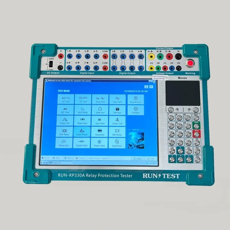
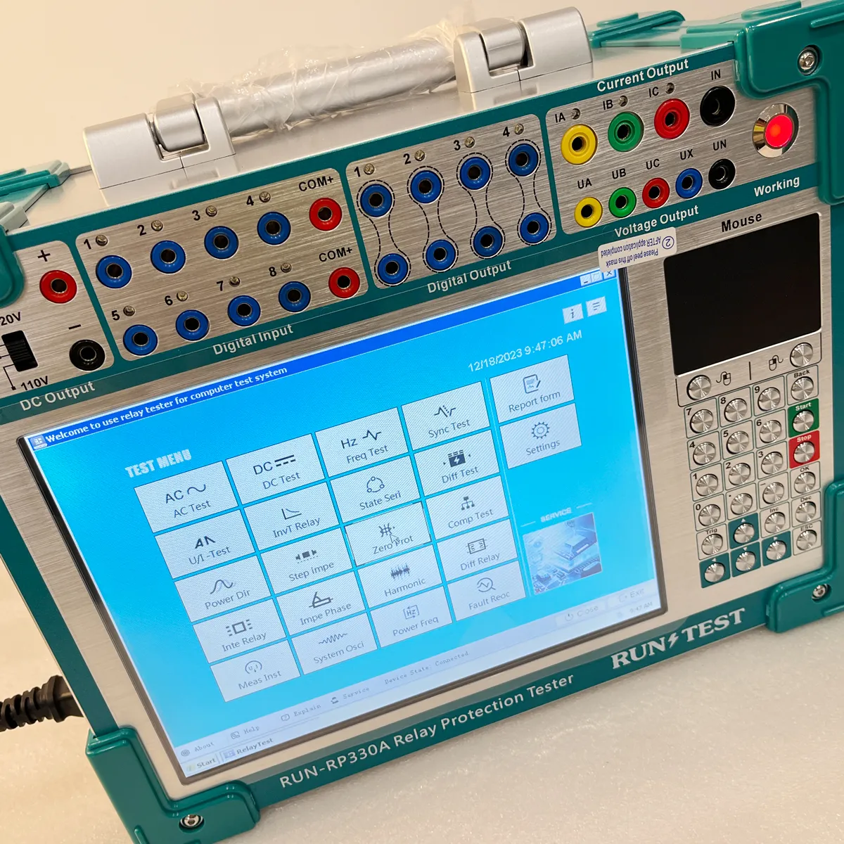
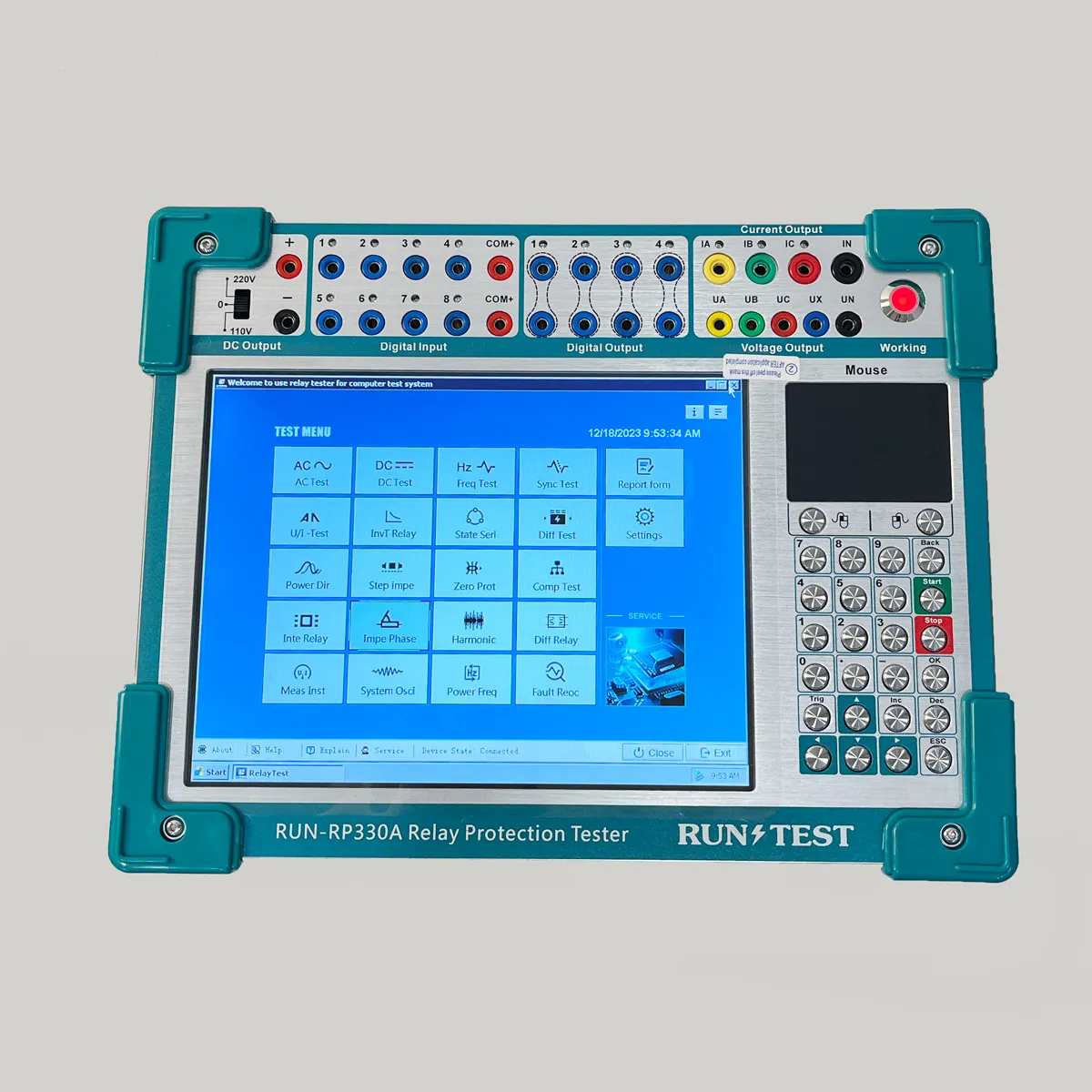
● This is new model 3 phase relay protection tester. The relay tester can test various AC and DC, current, voltage, intermediate, self-holding, signal and other single relays and the entire group. High degree of intelligence, Comprehensive self-check, self-protection function.
● Service
The instrument will be repaired and replaced free of charge for product quality problems within one year from the date of purchase, and will provide lifetime warranty and
technical services. If you find any abnormalities or malfunctions in the instrument, please contact the company in time to arrange the most convenient solution for you.


Characteristics of 3 Phase Relay Test Set Relay Protection Test Set
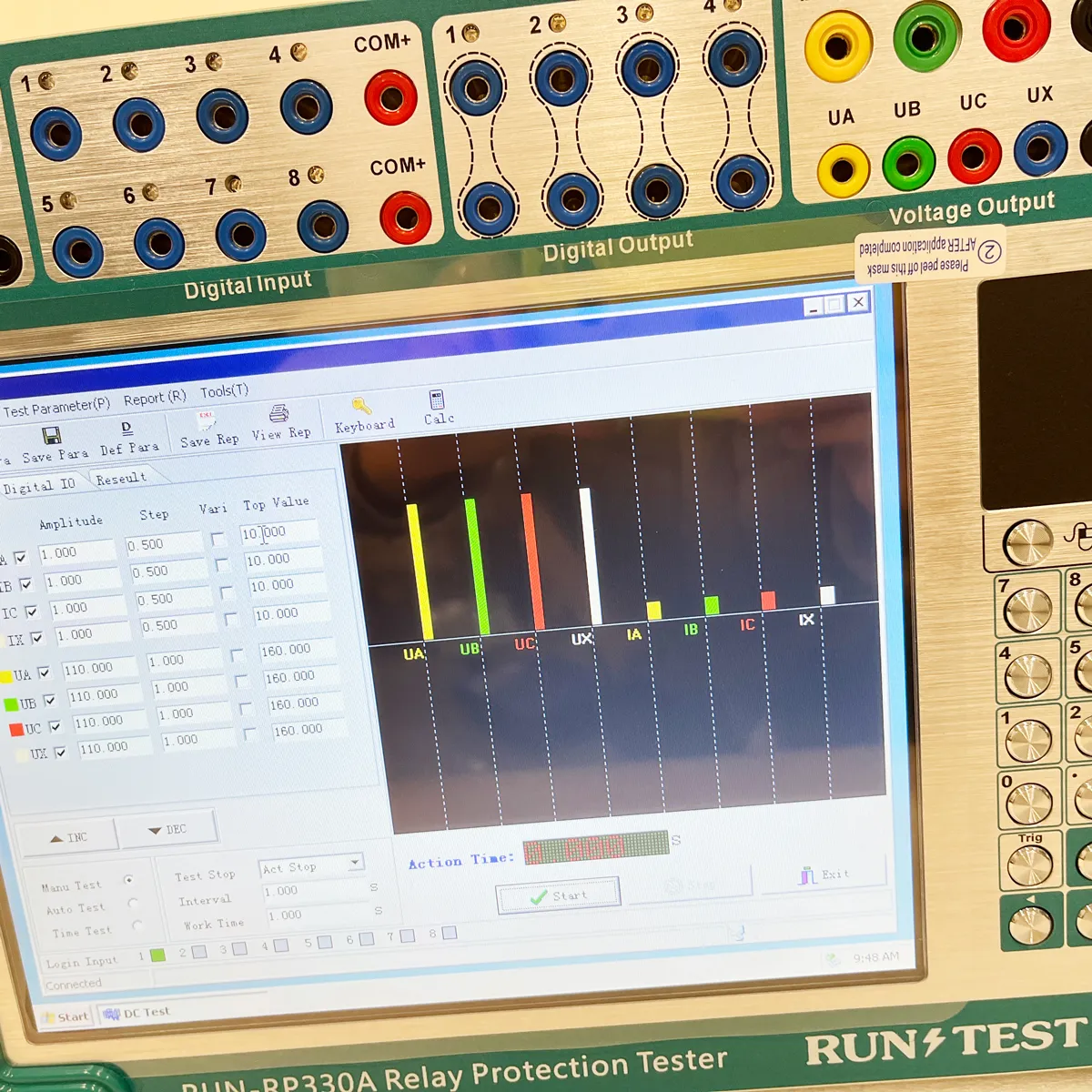
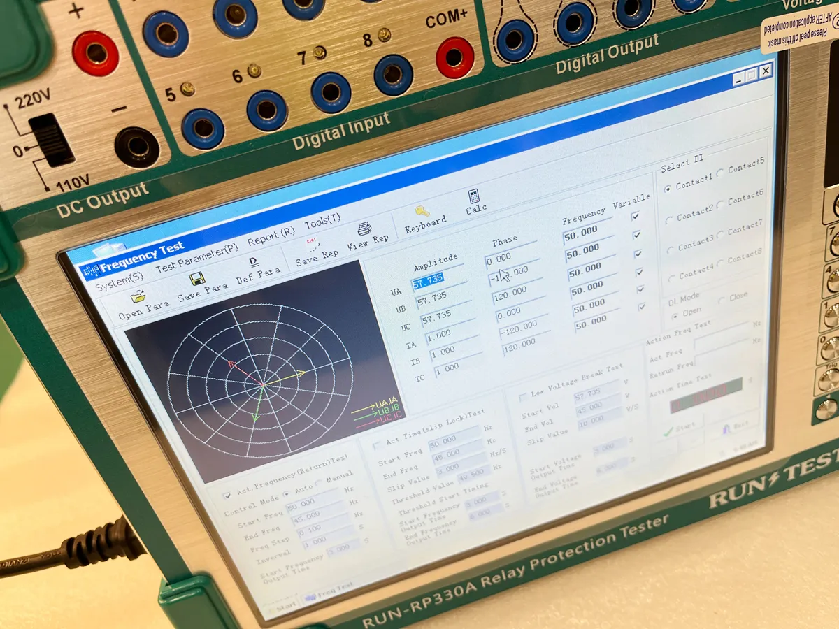
1. 4 phase voltage and 3 phase current output. It can test not only various traditional relays and protection devices, but also various modern microcomputer protections, especially for transformer differential protection and standby automatic switching device. The test is more convenient and perfect. 2. Classic Windows system operation interface, friendly man-machine interface, easy and fast operation; high performance embedded industrial control computer and 10.4-inch resolution 800 × 600 TFT true color display screen, can provide rich and intuitive information, including the current working state of the equipment and various help information. 3. The Three Phase Relay Tester in Windows XP system has Self-recovery function to avoid system crash caused by illegal shutdown or mis operation. 4. Equipped with ultra-thin industrial keyboard and photoelectric mouse, it can complete all kinds of operations through keyboard or mouse just like PC. 5. The main control board adopts DSP + FPGA structure and 16 bit DAC output. It can generate 2000 high density sine wave per cycle for fundamental wave, which greatly improves the quality of waveform and the accuracy of the tester. 6. The high-fidelity linear power amplifier ensures the accuracy of small current and the stability of large current. 7. USB interface is used to communicate with PC directly without any connecting line. 8. It has the function of GPS synchronization test. The device can be built-in GPS synchronous card (optional) and connected with PC through RS232 port to realize synchronous test of two testers in different places. 9. Equipped with independent dedicated DC auxiliary voltage source output, the output voltage is 110V (1A), 220V (0.6A). It can be used for relays or protection devices that need DC power supply. 10. It has the function of software self-calibration, which avoids opening the case to calibrate the accuracy by adjusting the potentiometer, thus greatly improving the stability of accuracy.
Technical parameters for the Secondary Current Injection Test Set
1. AC current Output
2. DC current Output
3. AC voltage output
4. DC voltage output
5. Numbers of Switch& Measuring time range
انظر مجموعة اختبار مرحل 3 مراحل الترحيلكتالوج للمزيد.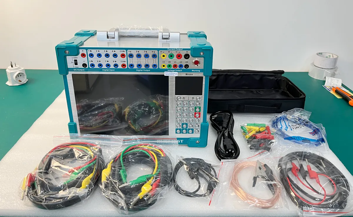

| خرج التيار أحادي الطور (RMS) | 0 - 30 أمبير/مرحلة، الدقة: 0.21 تيرابايت 3 تيرابايت ± 5 مللي أمبير |
| ثلاثة تيارات في الخرج المتوازي (RMS) | 0 - 90 أمبير / ثلاثي الطور في خرج متوازي الطور |
| دورة العمل | 10A |
| الطاقة القصوى للإخراج لكل مرحلة | 300 فولت أمبير |
| طاقة الخرج القصوى للتيار المتوازي ثلاثي الأطوار | 800 فولت أمبير |
| Maximum output allowable working time of triple parallel current | 5s |
| نطاق التردد | 0 - 1000 هرتز، الدقة 0.01 هرتز |
| الرقم التوافقي | 2-20 مرة |
| المرحلة | 0-360 o الدقة: 0.1 o |
| خرج التيار المستمر | 0 - ± 10 أمبير / الطور، الدقة: 0.21 تيرابايت 3 تيرابايت ± 5 مللي أمبير |
| خرج الجهد أحادي الطور (RMS) | 0 - 120 فولت / مرحلة، الدقة: 0.21 ت فولت ± 5 ميجا فولت |
| خرج جهد الخط (RMS) | 0--240V |
| طاقة خرج جهد الطور/خط الجهد الكهربي | 75 فولت أمبير/100 فولت أمبير |
| نطاق التردد | 0 - 1000 هرتز، الدقة: 0.001 هرتز |
| موجة متناسقة | 2-20 مرة |
| المرحلة | 0-360o الدقة: 0.1 o |
| سعة خرج الجهد أحادي الطور | 0--± 160V, accuracy: 0.2% ± 5mv |
| سعة خرج جهد الخط | 0--±320V |
| طاقة خرج جهد الطور/خط الجهد الكهربي | 90 فولت أمبير/180 فولت أمبير |
| تبديل طرف الإدخال | 8 قنوات |
| التلامس الهوائي | 1 - 20 مللي أمبير، 24 فولت، خرج نشط داخلي للجهاز |
| الانعكاس المحتمل | Passive contact: low resistance short circuit signal Active contact: 0-250V DC |
| تبديل طرف الإخراج | 4 أزواج، بدون تلامس، سعة الكسر: 110 فولت / 2 أمبير، 220 فولت / 1 أمبير |
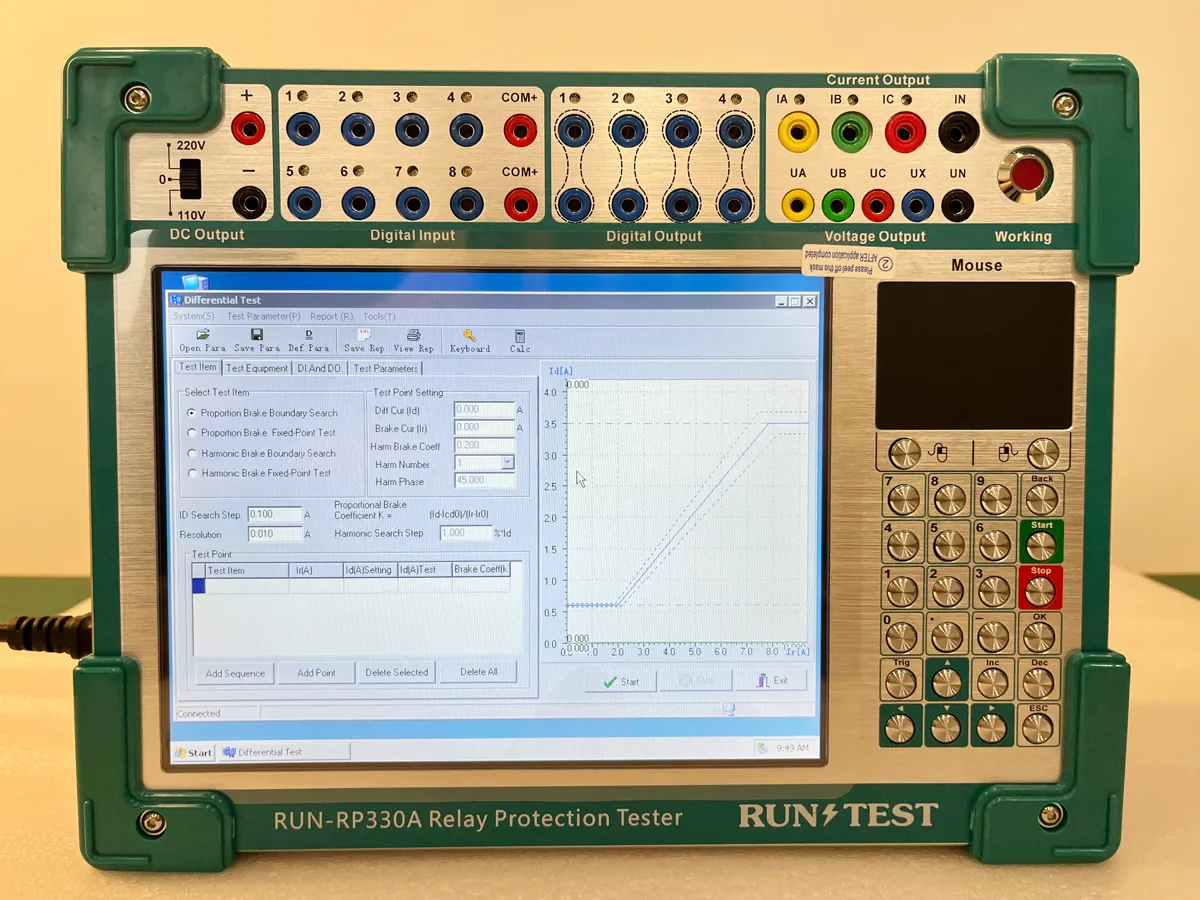
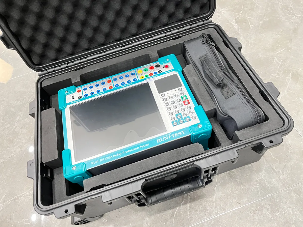
Equipment Show about the Protection Microcomputer Relay Test Set
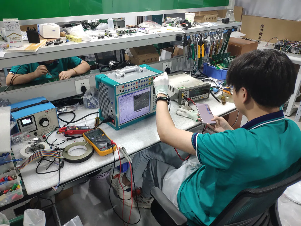
Factory Show about the relay tester