
cable fault locator
Cable Fault Locator is a device used to detect and locate faults in electrical cables. It helps in identifying issues like short circuits, open circuits, insulation faults, or other defects in underground, overhead, or buried cables. The goal is to pinpoint the exact location of the fault to minimize downtime and reduce the cost and labor required for cable repairs.
-
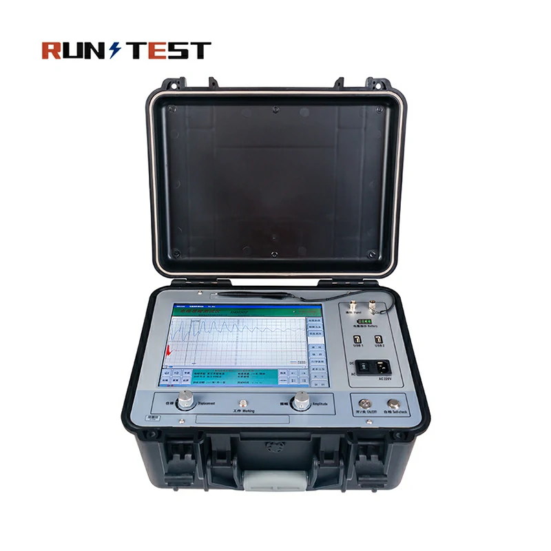
All-in-One Automatic High Voltage Tdr Underground Cable Fault Locator
-
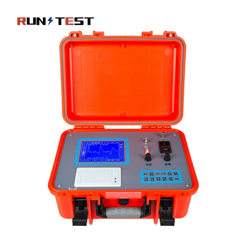
China Best Quality Portable Integration Underground Cable Fault Distance Locator
-
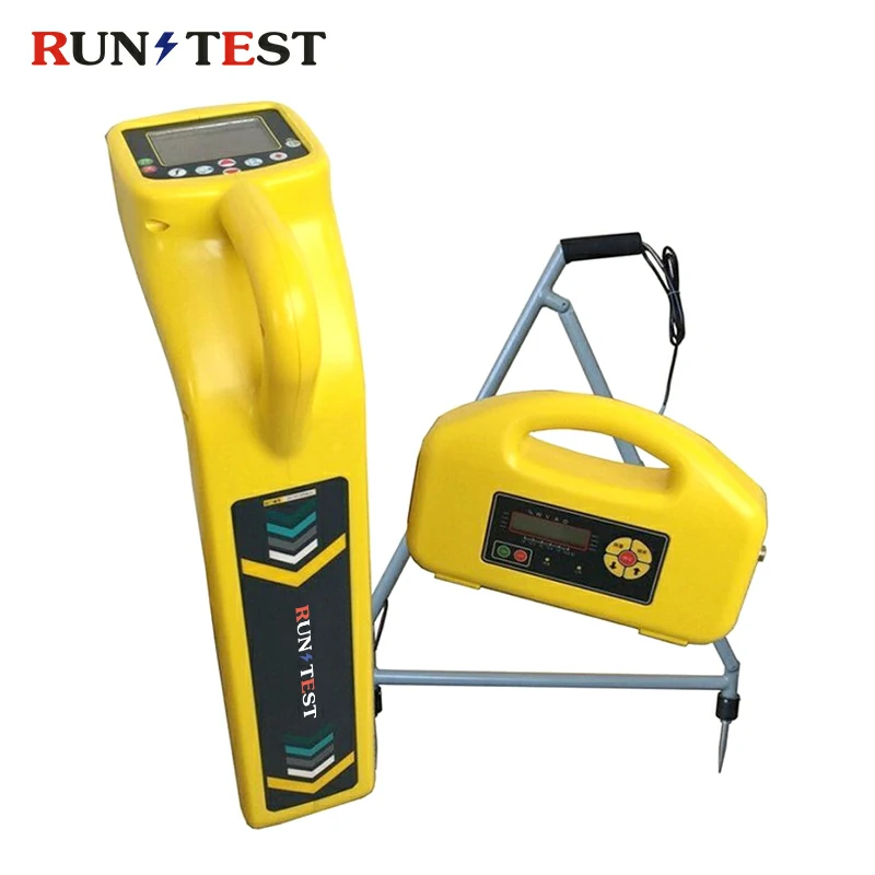
Underground Cable Fault Locator and Pipeline Detector
Cable fault tester could play a vital role in keeping electrical and telecommunication systems reliable. They use methods like Time Domain Reflectometry, Surge Testing, and Acoustic Fault Location to find cable faults accurately. This helps teams fix problems faster and more effectively. As a result, systems experience less downtime, repair costs drop, and overall reliability improves.
Modern Cable Fault Locators: Features and Applications
Features
- Display Screen: This makes it obvious what exactly is wrong, most often given by some units.
- Distance Measurement: With the locator, you could determine and display the real distance that is between your test point and the fault place.
- Multiple Fault Detection: Some of the advanced cables fault locators could be used to detect multiple flaws in a cable simultaneously.
- Data Logging: Some particular models are capable of recording particular data that you can use later to review and analyz.
- Adaptability: They can be used with various cables such as low-voltage or high-voltage; it does not matter to the units.
- Accuracy: They pinpoint faults very precisely. This way, you don’t have to dig up or test a large area.
Applications
- Electrical Utilities: People use cable fault locators to find problems in underground power cables.
- Telecommunication: Technicians use them to detect faults in network cables, fiber-optic cables, and more.
- Industrial Plants: Workers test cables inside big factories and facilities with these locators.
- Mining: Miners rely on them to identify cable faults during underground operations.
- Street Lighting: Crews use cable fault locators to locate faults in underground street lighting systems.
Types of Cable Faults
Power and communication networks experience various disruptions. Identifying the specific fault type helps engineers select the proper diagnostic approach.
-
Open Circuit Fault
An open circuit fault happens when a cable conductor breaks completely. This disruption stops the electrical current from flowing to the destination. Mechanical digging or ground shifting typically causes these breaks. Technicians easily identify this issue because the loop resistance becomes infinitely high.
-
Short Circuit Fault
A short circuit occurs when insulation failure brings two or more conductors into direct contact. Current bypasses the intended load and flows through this low-resistance path. This issue causes immediate system trips. Overloading or physical damage usually degrades the core insulation.
-
Ground Fault
A ground fault arises when a conductor connects physically with the earth or a grounded sheath. Current leaks directly into the ground, creating severe safety risks. This problem often follows water ingress or external mechanical piercing of the outer protective layers.
-
High Resistance Fault
High resistance faults feature a fault resistance value significantly higher than the characteristic impedance of the cable. Standard low-voltage test pulses cannot bridge this gap. Pinpointing these locations requires high-voltage surge generators to create a visible arc breakdown.
-
Low Resistance Fault
A low resistance fault shows a resistance value lower than or equal to the characteristic impedance of the cable. The damaged point directly affects low-voltage signals without requiring high-voltage stress. Technicians resolve these issues quickly using basic pulse reflection methods.
-
Flashover Fault
Flashover faults only appear when the system experiences high operating voltage. The insulation resistance seems perfect under low-voltage testing conditions. However, when voltage increases, an electrical arc jumps across the damaged area, causing an immediate circuit trip.
-
Sheath Fault
A sheath fault involves damage strictly to the outer protective jacket of the cable. Moisture enters the internal layers through these cracks, causing rapid insulation decay. Locating sheath defects early prevents minor issues from turning into major core failures.
-
Insulation Breakdown
Insulation breakdown marks the progressive chemical or thermal decay of the dielectric material. The cable leaks current continuously until a full short circuit or ground fault develops. Regular preventive testing helps identify this degradation before total breakdown occurs.
Cable Fault Location Methods
Different cable defects require specific technological approaches. Modern electrical test equipment combines these six key methods to achieve precision in the field.
-
TDR (Time Domain Reflectometry)
-
Working Principle: The instrument transmits a low-voltage electrical pulse down the cable loop. The pulse reflects back when it hits impedance changes.
-
Applicable Faults: Low resistance faults, open circuits, and total cable cuts.
-
Pros & Cons: Safe and highly accurate for simple breaks. However, it cannot detect high resistance or flashover faults.
-
-
Pulse Reflection Method
-
Working Principle: This approach uses high-voltage surge equipment to initiate a breakdown at the fault point, reflecting a high-frequency pulse wave back.
-
Applicable Faults: High resistance, flashing faults, and severe insulation degradation.
-
Pros & Cons: Locates complex underground faults effectively. However, it subjects the cable insulation to high-voltage stress.
-
-
Impulse Current Method
-
Working Principle: A surge capacitor discharges into the cable, creating a transient current wave. Inductive couplers collect this signal data safely.
-
Applicable Faults: Extreme high-resistance faults and flashovers in high-voltage networks.
-
Pros & Cons: Separates high-voltage circuits from the control panel. The complex waveforms require experienced operators to interpret correctly.
-
-
Acoustic Method
-
Working Principle: A surge generator injects periodic high-voltage pulses to create a loud physical spark at the underground fault location. Ground microphones pick up this sound.
-
Applicable Faults: Precise pinpointing of high resistance and flashover faults in buried cables.
-
Pros & Cons: Pinpoints the exact physical location perfectly. However, environmental noise can interfere with the acoustic signal.
-
-
Bridge Method
-
Working Principle: This classic technique balances electrical resistance loops via a high-voltage Wheatstone bridge to calculate fault distance mathematically.
-
Applicable Faults: Uniform low resistance faults and core-to-core short circuits.
-
Pros & Cons: Highly accurate and independent of cable length. It requires a healthy return conductor wire to function.
-
-
Traveling Wave Method
-
Working Principle: The system captures high-speed transient voltage waves generated instantly at the fault moment, measuring travel time across sensors.
-
Applicable Faults: Online tracking for long-distance transmission lines.
-
Pros & Cons: Captures real-time fault data instantly. It requires expensive high-speed monitoring hardware installations.
-
Product Advantages
Our product line delivers industry-leading field performance across eight major benefit vectors:
-
High Accuracy Positioning: Reduces digging areas with a pin-pointing error margin of less than 0.1 meters.
-
Fast Fault Detection: Locates long-distance faults within minutes using automatic waveform calculation systems.
-
Multi-mode Testing: Combines TDR, acoustic tracking, and impulse current methods within a single system.
-
Intelligent Analysis: Displays clear distance markers automatically without requiring manual waveform geometry calculations.
-
Portable Design: Utilizes ultra-light military-grade housing for easy transport across rugged substation terrains.
-
Large LCD Display: Features high-brightness color touch screens readable under direct outdoor sunlight conditions.
-
Long Battery Life: Operates up to 10 hours continuously using high-capacity lithium-ion power packs.
-
IEC Compliant: Matches rigorous international electrical engineering safety protocols for high-voltage testing environments.
Technical Features Matrix
Our comprehensive series offers stable parameters across all operational models:
| Parameter | Operational Performance Range |
| Detection Distance | 0 to 100 km range |
| Positioning Accuracy | ±0.1% or ±10cm margin |
| Display Interface | High-definition LCD Touch Screen |
| Power Supply | High-capacity Rechargeable Lithium Battery |
| Data Storage | Internal Memory Expansion Slot |
| Communication Interface | USB Data Export Port |
How to Choose a Cable Fault Locator
Selecting the right cable fault locator requires matching product capabilities with your specific distribution network. Evaluate these six essential vectors before buying:
1. Voltage Level
High-voltage transmission lines require robust surge generators capable of hitting 32kV or 35kV targets. Conversely, low-voltage industrial control cables only need compact 4kV to 8kV injection units to spark fault points safely.
2. Cable Type
Armored power cables absorb acoustic signals quickly, requiring high surge energy outputs (up to 2048 Joules). Unarmored telecom lines require high-resolution TDR units to identify minor copper defects without using high voltage.
3. Fault Type
If you face frequent open circuits, buy a standalone TDR locator. For complex, moisture-driven intermittent flashover faults, purchase a combined system that features integrated high-voltage surge capacitors and acoustic receivers.
4. Testing Distance
Short factory cable networks require tight spatial resolution to differentiate close connection joints. Long-distance submarine or cross-country cables demand powerful signal transmitters that maintain clear pulse paths across 50 to 100 kilometers.
5. Portable or Vehicle-Mounted
Field teams managing urban underground networks need ultra-portable, battery-powered suitcase designs. Regional utilities managing vast infrastructure should invest in vehicle-mounted integrated test vans for maximum system capability.
6. Underground or Overhead
Overhead lines benefit from traveling wave systems that isolate atmospheric lightning damage quickly. Buried cables require precise acoustic-magnetic step-voltage pinpointers to find faults through layers of soil or concrete.
Industry Standards & Compliance
We build and qualify our diagnostic hardware according to strict international compliance frameworks:
-
IEC 60229: Guides testing procedures for outer protective sheaths on power cables.
-
IEC 60502: Governs insulation performance parameters for extruded solid dielectric power cables.
-
IEEE Standards: Aligns equipment with IEEE 400 guidelines for field-testing shielded cable systems.
-
CE Compliance: Meets all European electrical safety and electromagnetic emission restrictions.
-
ISO9001: Validates that our manufacturing facility adheres to strict quality management system workflows.
Calibration & Accuracy Assurance
Maintaining measurement accuracy is essential for high-voltage field testing. We support our equipment with four core quality-assurance programs:
-
Factory Calibration: Every unit undergoes multi-point timing and voltage calibration against reference atomic clocks before leaving production.
-
Accuracy Verification: We run every instrument through a 10km real-cable test loop to verify distance calculations.
-
Calibration Certificate: Your shipment includes a comprehensive calibration document traceable to international metrology standards.
-
Periodic Recalibration Recommendation: We recommend returning the instrument every 12 months for routine service to maintain compliance.
Related Test Equipment
To manage complete power facility maintenance, explore our other industrial test systems:
-
Transformer Tester: Comprehensive analysis systems for power transformer insulation and winding integrity.
-
CT PT Analyzer: Automated excitation and ratio testers for protective instrument transformers.
-
Transformer Turns Ratio Meter: High-precision meters checking transformer voltage conversion ratios.
-
Relay Tester: Advanced multi-phase test sets calibrating grid protection relays.
FAQ
Q1: What is a cable fault locator?
A: It is a professional test system that detects, pre-locates, and pinpoints insulation failures in underground or overhead cables.
Q2: How does a cable fault locator work?
A: The system injects low-voltage pulses or high-voltage surges into the cable. It measures pulse reflection times to calculate the fault distance.
Q3: What cable faults can be detected?
A: Our systems identify open circuits, short circuits, low resistance paths, high resistance faults, sheathing tears, and high-voltage flashovers.
Q4: What is the difference between TDR and surge testing?
A: TDR utilizes safe low-voltage signals for simple breaks. Surge testing applies high-voltage thumping to create sparks at high-resistance faults.
Q5: Can underground cable faults be accurately located?
A: Yes. Combining TDR pre-location with acoustic-magnetic ground microphones narrows the final digging area down to less than 10 centimeters.
Q6: What voltage levels are supported?
A: Our product catalog features portable units starting at 4kV up to heavy-duty utility systems delivering 35kV outputs.
Q7: Is calibration required?
A: Yes. We recommend annual calibration to maintain system accuracy and comply with international industrial audit requirements.
Q8: Can the system generate test reports?
A: Yes. The instrument saves testing waveforms internally. Operators can export this data via USB to create PDF reports.
Q9: How accurate is the fault distance?
A: The pre-location system delivers a tight accuracy class of ±0.1% across the entire length of the tested cable.
Q10: Do you provide operator training?
A: Yes. We support your purchase with detailed video tutorials, online video engineering sessions, and complete technical documentation.
Why Choose Voltage Tester
Choosing Voltage Tester connects your business with an experienced manufacturer of high-voltage diagnostic equipment. Our specialized R&D team comprises senior power engineering experts who integrate digital signal processing with rugged high-voltage design. We manage an advanced calibration laboratory to ensure every instrument matches international tolerances before shipment.
Our facility runs on a strict ISO quality system, checking raw materials and finished products thoroughly. With over ten years of global export experience, we deliver compliant systems to power utilities and industrial complexes worldwide. Our team supports your procurement with fast global delivery, full OEM customization, and lifetime technical assistance.